Table of Contents
Advertisement
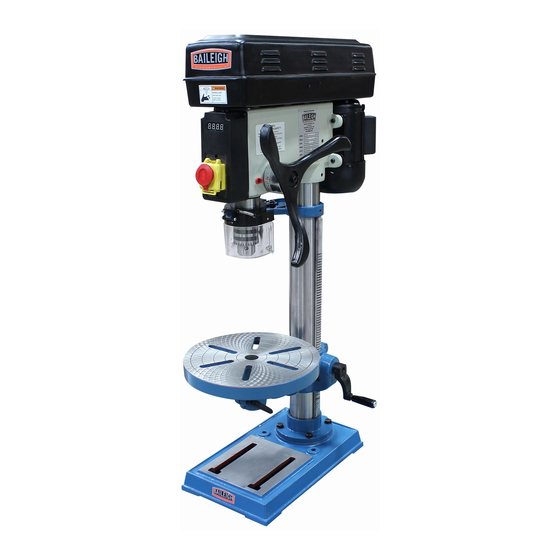
MODEL: DP-1512B-HD AND DP-1512F-HD
REPRODUCTION OF THIS MANUAL IN ANY FORM WITHOUT WRITTEN APPROVAL OF BAILEIGH INDUSTRIAL, INC.
IS PROHIBITED. Baileigh Industrial, Inc. does not assume and hereby disclaims any liability for any damage or loss
caused by an omission or error in this Operator's Manual, resulting from accident, negligence, or other occurrence.
DRILL PRESS
Baileigh Industrial, Inc.
P.O. Box 531
Manitowoc, WI 54221-0531
Phone: 920.684.4990
Fax: 920.684.3944
sales@baileigh.com
© 2016 Baileigh Industrial, Inc.
OPERATOR'S
MANUAL
Rev. 06/2016
Advertisement
Table of Contents

Related Manuals for Baileigh DP-1512B-HD


Summary of Contents for Baileigh DP-1512B-HD
-
Page 1: Drill Press
REPRODUCTION OF THIS MANUAL IN ANY FORM WITHOUT WRITTEN APPROVAL OF BAILEIGH INDUSTRIAL, INC. IS PROHIBITED. Baileigh Industrial, Inc. does not assume and hereby disclaims any liability for any damage or loss caused by an omission or error in this Operator’s Manual, resulting from accident, negligence, or other occurrence. -
Page 2: Table Of Contents
LUBRICATION AND MAINTENANCE ................28 Greasing the Machine ....................28 Storing Machine for Extended Period of Time ............29 WIRING DIAGRAM ....................... 29 DP-1512B-HD PARTS DIAGRAM ................. 30 DP-1512B-HD Parts List ....................31 DP-1512F-HD PARTS DIAGRAM ................. 33 DP-1512F-HD Parts List ....................34... -
Page 3: Thank You & Warranty
THANK YOU & WARRANTY Thank you for your purchase of a machine from Baileigh Industrial. We hope that you find it productive and useful to you for a long time to come. Inspection & Acceptance. Buyer shall inspect all Goods within ten (10) days after receipt thereof. Buyer’s payment shall constitute final acceptance of the Goods and shall act as a waiver of the Buyer’s rights to inspect or reject the... - Page 4 Baileigh Industrial makes every effort to ensure that our posted specifications, images, pricing and product availability are as correct and timely as possible. We apologize for any discrepancies that may occur. Baileigh Industrial reserves the right to make any and all changes deemed necessary in the course of business including but not limited to pricing, product specifications, quantities, and product availability.
-
Page 5: Introduction
INTRODUCTION The quality and reliability of the components assembled on a Baileigh Industrial machine guarantee near perfect functioning, free from problems, even under the most demanding working conditions. However if a situation arises, refer to the manual first. If a solution cannot be found, contact the distributor where you purchased our product. -
Page 6: Safety Instructions
IMPORTANT PLEASE READ THIS OPERATORS MANUAL CAREFULLY It contains important safety information, instructions, and necessary operating procedures. The continual observance of these procedures will help increase your production and extend the life of the equipment. SAFETY INSTRUCTIONS LEARN TO RECOGNIZE SAFETY INFORMATION This is the safety alert symbol. - Page 7 SAVE THESE INSTRUCTIONS. Refer to them often and use them to instruct others. PROTECT EYES Wear safety glasses or suitable eye protection when working on or around machinery. PROTECT AGAINST NOISE Prolonged exposure to loud noise can cause impairment or loss of hearing.
-
Page 8: Safety Precautions
All Baileigh woodworking machines should be used only for their intended use. Baileigh does not recommend or endorse making any modifications or alterations to a Baileigh machine. Modifications or alterations to a machine may pose a substantial risk of injury to the operator or others and may do substantial damage to the machine. - Page 9 7. Drill Operation. Never start the drill press with the drill bit pressed against the piece part. Feed the drill bit slowly and evenly into the piece part. Position work to avoid drilling into the table. 8. Clearing Chips. Turn the machine OFF and clear chips and scrap pieces with a brush or with compressed air.
- Page 10 24. Inspect power and control cables periodically. Replace if damaged or bare wires are exposed. Bare wiring can kill! 25. Keep children away. Children must never be allowed in the work area. DO NOT let them handle machines, tools, or extension cords. Keep visitors a safe distance from the work area.
-
Page 11: Technical Specifications
(other than die sets and blades). For specific application needs or future machine purchases contact the Sales Department at: sales@baileigh.com, Phone: 920.684.4990, or Fax: 920.684.3944. Note: The photos and illustrations used in this manual are representative only and may not depict the actual color, labeling or accessories and may be intended to illustrate technique only. -
Page 12: Unpacking And Checking Contents
UNPACKING AND CHECKING CONTENTS Your Baileigh machine is shipped complete. Separate all parts from the packing material and check each item carefully. Make certain all items are accounted for before discarding any packing material. WARNING: SUFFOCATION HAZARD! Immediately discard any plastic bags and packing materials to eliminate choking and suffocation hazards to children and animals. - Page 13 Separate all parts from packaging materials and check each Item make sure all items are accounted for before discarding any packing material. Item Description Qty. Table Column Support Arm Owner's Manual Bag of Loose Parts Base Head Assembly...
-
Page 14: Transporting And Lifting
TRANSPORTING AND LIFTING IMPORTANT: Lifting and carrying operations should be carried out by skilled workers, such as a truck operator, crane operator, etc. If a crane is used to lift the machine, attach the lifting chain carefully, making sure the machine is well balanced. Follow these guidelines when lifting with truck or trolley: ... -
Page 15: Installation
INSTALLATION IMPORTANT: Consider the following when looking for a suitable location to place the machine: Overall weight of the machine. Weight of material being processed. Sizes of material to be processed through the machine. Space needed for auxiliary stands, work tables, or other machinery. ... -
Page 16: Anchoring The Machine
.31" rods that connect through holes in the base of the stand. (7.87mm) If you intend to mount the Baileigh machine on a workbench be .50" aware of the following: (12.7mm) ... -
Page 17: Assembly And Set Up
ASSEMBLY AND SET UP WARNING: For your own safety, DO NOT connect the machine to the power source until the machine is completely assembled and you read and understand the entire instruction manual. Most of your Drill Press has been assembled at the factory, but some parts must be assembled or installed after delivery. - Page 18 13. Using a lifting device or an assistant, lift the head assembly over the column and insert the column into the pocket on the bottom of the head assembly until the column is fully seated into the head pocket, approximately 4” (100mm). 14.
- Page 19 21. Install the chuck guard onto the spindle shaft until the bottom edge of the guard is flush with the bottom edge of the spindle. 22. Firmly tighten the clamping screw but do not over tighten and break the c lamping ring.
-
Page 20: Drill Chuck And Arbor
Drill Chuck and Arbor The drill chuck attaches to the drill spindle by means of a drill chuck arbor. Matched tapers on the arbor and chuck bore create solid assembly when properly joined. To assemble the drill chuck and mount it to the spindle, carefully follow the instructions below: IMPORTANT: The drill chuck, arbor and... - Page 21 Arbor Removal A drift key is included to aid in the drill chuck arbor removal. 1. Extend the spindle downward until the slot is exposed in the side of the quill. 2. Rotate the spindle until the inner slot is aligned with the outer as shown.
-
Page 22: Electrical
ELECTRICAL CAUTION: HAVE ELECTRICAL UTILITIES CONNECTED TO MACHINE BY A CERTIFIED ELECTRICIAN! Check if the available power supply is the same as listed on the machine nameplate. WARNING: Make sure the grounding wire (green) is properly connected to avoid electric shock. DO NOT switch the position of the green grounding wire if any electrical plug wires are switched during hookup. -
Page 23: Power Cord Connection
Improper connection of the equipment-grounding conductor can result in risk of electric shock. The conductor with insulation having an outer surface that is green with or without yellow stripes is the equipment-grounding conductor. If repair or replacement of the electric cord or plug is necessary, do not connect the equipment-grounding conductor to a live terminal. -
Page 24: Operating Precautions
OPERATING PRECAUTIONS The following operating and safety precautions must be observed in order to avoid harm to the operator or damage to the drill press. 1. Safety is the responsibility of the user/purchaser since conditions differ between jobs. Use and enforce safety procedures at each operation location and provide for any changes in conditions to provide maximum safety. -
Page 25: Drilling Recommendations
8. Use the adjustment knob on the left side of the drill head to adjust the spindle speed as needed. IMPORTANT: Never adjust the spindle speed when the drill is stopped. Only adjust the spindle speed when the drill is running safely at full power. -
Page 26: Indication Of Extreme Speeds And Feeds
Indication of Extreme Speeds and Feeds A drill that splits up the web is evidence of too much feed or insufficient tip clearance at the center as a result of improper grinding. The rapid wearing away of the extreme outer comers of the cutting edges indicates that the speed is too high. -
Page 27: Alignment Pointer Adjustment
Alignment Pointer Adjustment This machine is equipped with an alignment pointer. The pointer is used to indicated the point on the material that the tip of the drill (center point of the drilled hole) contact first. 1. Set up the drill with the desired bit, and position the table and material as needed to create the first drill location. -
Page 28: Machine Adjustment
MACHINE ADJUSTMENT WARNING: Make sure the power cord is disconnected and power is OFF before working on the machine. Always follow proper safety precautions when working on or around any machinery. Depth Stop Your drill press comes with a depth stop adjustment for use when drilling. -
Page 29: Table Adjustment
Table Adjustment The table can be adjusted for height, rotation and angle. 1. Loosen the support bracket lock knob. Turn the table hand crank to lift or lower the table. 2. Always lock the support bracket in place before operating the machine. Adjust rotation: 1. -
Page 30: Lubrication And Maintenance
LUBRICATION AND MAINTENANCE WARNING: Make sure the electrical disconnect is OFF before working on the machine. Maintenance should be performed on a regular basis by qualified personnel. Always follow proper safety precautions when working on or around any machinery. Daily Maintenance ... -
Page 31: Storing Machine For Extended Period Of Time
Storing Machine for Extended Period of Time If the Drill Press is to be inactive for a long period of time, prepare the machine as follows: Detach the plug from the electrical supply panel. Clean and grease the machine. ... -
Page 32: Dp-1512B-Hd Parts Diagram
DP-1512B-HD PARTS DIAGRAM... -
Page 33: Dp-1512B-Hd Parts List
DP-1512B-HD Parts List Item Description Qty. Item Description Qty. Base Wedge Screw Screw Spring Washer Rack Self-Tapping Screw Column Screw Collar Screw Flange Nut Crank Screw Screw Protect Mirror Upper Fork Seat Washer Knob Screw Spring Bolt Spring Washer Screw... - Page 34 Item Description Qty. Item Description Qty. Screw Line Clip Indicator Bolt Screw Washer Screw Plug Screw Allen Key Screw Allen Key Insulation Board Screw Scale Rivet Scale Screw Spring Washer Gear Shaft Digital Display Hand Wheel Sensor Support Bolt Screw Washer Screw Retaining Ring...
-
Page 35: Dp-1512F-Hd Parts Diagram
DP-1512F-HD PARTS DIAGRAM... -
Page 36: Dp-1512F-Hd Parts List
DP-1512F-HD Parts List Item Description Qty. Item Description Qty. Base Pulley Cover Bolt Bearing Seat Rack Bearing Column Lower Movable Pulley (middle) 1 Collar Screw Screw Fixed Pulley (Middle) Table Support Seat Upper Movable Pulley (middle) 1 8 – 12 Crank Assembly Rubber Washer Lock Handle Rubber Washer... - Page 37 Item Description Qty. Item Description Qty. Screw Plastic Seat Bolt Sensor Switch Screw Plastic Plate Flat Washer Switch Box Digital Display Set Sensor Support 119, Terminal Retaining Ring Copper Retaining Ring Grounding Mark Bearing Start Washer Bushing Screw Shaft Screw Retaining Spring Screw Hex Socket Screw...
- Page 38 Item Description Qty. Item Description Qty. Speed Range Label Micro-Switch Cable Allen Key Pan Head Screw Allen Key Terminal Screw Insulator Spring Seat Plate Key Quill Spring Plate Key Spring Cover Plate Key Screw Fixed Pulley (Motor) Self-Tapping Screw Movable Pulley (Motor) Pan Head Screw Spring Flange Nut...
- Page 39 NOTES...
- Page 40 , WI 54220 UFEK RIVE ANITOWOC : 920. 684. 4990 F : 920. 684. 3944 HONE BAILEIGH BAILEIGH INDUSTRIAL, INC. 1455 S. C , CA 91761 AMPUS VENUE NTARIO : 920. 684. 4990 F : 920. 684. 3944 HONE BAILEIGH INDUSTRIAL LTD. U...
Need help?
Do you have a question about the DP-1512B-HD and is the answer not in the manual?
Questions and answers