Table of Contents
Advertisement
Quick Links
OPERATOR'S
MANUAL
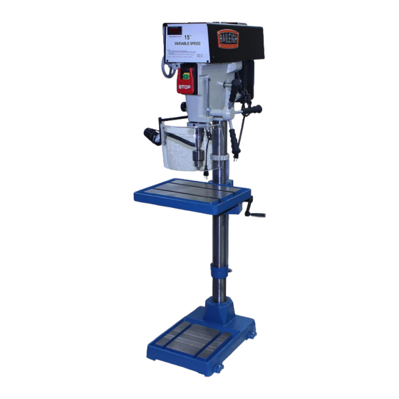
VARIABLE SPEED DRILL PRESS
MODEL: DP-15VSF
Baileigh Industrial Holdings LLC,
P.O. Box 531
Manitowoc, WI 54221-0531
Phone: 920.684.4990
Fax: 920.684.3944
sales@baileigh.com
REPRODUCTION OF THIS MANUAL IN ANY FORM WITHOUT WRITTEN APPROVAL OF BAILEIGH INDUSTRIAL
HOLDINGS LLC, IS PROHIBITED. Baileigh Industrial Holdings LLC, does not assume and hereby disclaims any
liability for any damage or loss caused by an omission or error in this Operator's Manual, resulting from accident,
negligence, or other occurrence.
Rev. 08/2020
© 2020 Baileigh Industrial Holdings LLC
Advertisement
Table of Contents

Subscribe to Our Youtube Channel
Related Manuals for Baileigh DP-15VSF


Summary of Contents for Baileigh DP-15VSF
- Page 1 REPRODUCTION OF THIS MANUAL IN ANY FORM WITHOUT WRITTEN APPROVAL OF BAILEIGH INDUSTRIAL HOLDINGS LLC, IS PROHIBITED. Baileigh Industrial Holdings LLC, does not assume and hereby disclaims any liability for any damage or loss caused by an omission or error in this Operator’s Manual, resulting from accident, negligence, or other occurrence.
-
Page 2: Table Of Contents
Table of Contents THANK YOU & WARRANTY ..................1 INTRODUCTION ......................3 GENERAL NOTES ......................3 SAFETY INSTRUCTIONS ....................4 SAFETY PRECAUTIONS ....................6 Dear Valued Customer: ....................6 TECHNICAL SUPPORT ....................9 TECHNICAL SPECIFICATIONS ................... 10 UNPACKING AND CHECKING CONTENTS ..............11 Cleaning ........................ -
Page 3: Thank You & Warranty
THANK YOU & WARRANTY Thank you for your purchase of a machine from Baileigh Industrial Holdings LLC. We hope that you find it productive and useful to you for a long time to come. Inspection & Acceptance. Buyer shall inspect all Goods within ten (10) days after receipt thereof. Buyer’s payment shall constitute final acceptance of the Goods and shall act as a waiver of the Buyer’s rights to inspect or... - Page 4 We apologize for any discrepancies that may occur. Baileigh Industrial Holdings LLC reserves the right to make any and all changes deemed necessary in the course of business including but not limited to pricing, product specifications, quantities, and product availability.
-
Page 5: Introduction
INTRODUCTION The quality and reliability of the components assembled on a Baileigh Industrial Holdings LLC machine guarantee near perfect functioning, free from problems, even under the most demanding working conditions. However, if a situation arises, refer to the manual first. If a solution cannot be found, contact the distributor where you purchased our product. -
Page 6: Safety Instructions
IMPORTANT PLEASE READ THIS OPERATORS MANUAL CAREFULLY It contains important safety information, instructions, and necessary operating procedures. The continual observance of these procedures will help increase your production and extend the life of the equipment. SAFETY INSTRUCTIONS LEARN TO RECOGNIZE SAFETY INFORMATION This is the safety alert symbol. - Page 7 SAVE THESE INSTRUCTIONS. Refer to them often and use them to instruct others. PROTECT EYES Wear safety glasses or suitable eye protection when working on or around machinery. PROTECT AGAINST NOISE Prolonged exposure to loud noise can cause impairment or loss of hearing.
-
Page 8: Safety Precautions
• All Baileigh woodworking machines should be used only for their intended use. • Baileigh does not recommend or endorse making any modifications or alterations to a Baileigh machine. Modifications or alterations to a machine may pose a substantial risk of injury to the operator or others and may do substantial damage to the machine. - Page 9 Please enjoy your Baileigh machine! ..Please enjoy it SAFELY! 1. FOR YOUR OWN SAFETY, READ INSTRUCTION MANUAL BEFORE OPERATING THE MACHINE. Learn the machine’s application and limitations as well as the specific hazards. 2. Only trained and qualified personnel can operate this machine.
- Page 10 16. Keep children away. Children must never be allowed in the work area. DO NOT let them handle machines, tools, or extension cords. 17. Keep visitors a safe distance from the work area. 18. Store idle equipment. When not in use, tools must be stored in a dry location to inhibit rust. Always lock up tools and keep them out of reach of children.
-
Page 11: Technical Support
(other than die sets and blades). For specific application needs or future machine purchases contact the Sales Department at: sales@baileigh.com, Phone: 920.684.4990, or Fax: 920.684.3944. Note: The photos and illustrations used in this manual are representative only and may not depict the actual color, labeling or accessories and may be intended to illustrate technique only. -
Page 12: Technical Specifications
TECHNICAL SPECIFICATIONS Description Floor Drill Press Type Belt drive 5/8” (16mm) Drilling Capacity Cast Iron Drilling Capacity Steel 1/2" (13mm) 15” (381mm) Swing Motor (Pre-Wired 115v) 1hp (.74kw), 115V/220V, 1ph, 60hz, 14/7A, 1730rpm Voltage 115V/220V, 1ph, 60hz (Pre-Wired 115V) Work Lamp Power 100V~240V (separate power plug from drill press.) Work Lamp 12V, 6W... -
Page 13: Unpacking And Checking Contents
UNPACKING AND CHECKING CONTENTS Your Baileigh machine is shipped complete. Separate all parts from the packing material and check each item carefully. Make certain all items are accounted for before discarding any packing material. WARNING: SUFFOCATION HAZARD! Immediately discard any plastic bags and packing materials to eliminate choking and suffocation hazards to children and animals. -
Page 14: Transporting And Lifting
TRANSPORTING AND LIFTING NOTICE: Lifting and carrying operations should be carried out by skilled workers, such as a truck operator, crane operator, etc. If a crane is used to lift the machine, attach the lifting chain carefully, making sure the machine is well balanced. Follow these guidelines when lifting with truck or trolley: •... -
Page 15: Anchoring The Machine
• Remove scrap and waste materials regularly, and make sure the work area is free from obstructing objects. • It is important to maintain free area around the machine, which is required for the working place. If any long material is machined, it is necessary to have a sufficient room in front of the machine as well behind it in the places of material input and output. -
Page 16: Getting To Know Your Machine
GETTING TO KNOW YOUR MACHINE... -
Page 17: Assembly And Set Up
Base Work Table Spindle Work Lamp Chuck Guard Interlock Switch (Not Visible) On/Off Switch Speed Setting Handle Wheel LED Speed Display Motor Head Locking Handle Quill Feed Handle Depth Stop Table Height Adjustment Column Table Height Adjustment Rack ASSEMBLY AND SET UP WARNING: For your own safety, DO NOT connect the machine to the power source until the machine is completely assembled and you read and... - Page 18 Head Positioning The Drill Press is shipped with the head in lowered position. 1. Position the drill press in the desired location and level and secure the drill press to prevent movement and tip over. 2. Install and secure the crank lever and the crank handle (A) onto the elevation shaft.
- Page 19 Raise the Rack 1. Position the 2x4 on the base and under the table (F) as shown and lower the table onto the 2x4. 2. Loosen the set screw (G) on the upper rack ring and raise rack ring 5” – 6” to allow clearance for the rack to raise.
-
Page 20: Electrical
ELECTRICAL CAUTION: HAVE ELECTRICAL UTILITIES CONNECTED TO MACHINE BY A CERTIFIED ELECTRICIAN! Check if the available power supply is the same as listed on the machine nameplate. WARNING: Make sure the grounding wire (green) is properly connected to avoid electric shock. DO NOT switch the position of the green grounding wire if any electrical plug wires are switched during hookup. -
Page 21: Power Cord Connection
• Improper connection of the equipment-grounding conductor can result in risk of electric shock. The conductor with insulation having an outer surface that is green with or without yellow stripes is the equipment-grounding conductor. If repair or replacement of the electric cord or plug is necessary, do not connect the equipment-grounding conductor to a live terminal. -
Page 22: Electrical Wiring Diagram
ELECTRICAL WIRING DIAGRAM Voltage Change This drill press is prewired for 115 volt input power, but can be converted to 220 volt input. This change requires that the motor and the DRO wiring be changed from 110V to 220V. 1. Verify that the drill press is disconnected from any power supply. 2. -
Page 23: Operating Controls
OPERATING CONTROLS CAUTION: Always wear proper eye protection with side shields, safety footwear, and leather gloves to protect from burrs and sharp edges. When handling large heavy material make sure they are properly supported. ON/OFF Switch The ON/OFF switch (A) is located at the front of the drill head. -
Page 24: Operating Precautions
OPERATING PRECAUTIONS The following operating and safety precautions must be observed in order to avoid harm to the operator or damage to the drill press. 1. The head assembly must be locked to the column so the thrust produced by drilling will not force the head assembly up the column. -
Page 25: Indication Of Extreme Speeds And Feeds
Indication of Extreme Speeds and Feeds A drill that splits up the web is evidence of too much feed or insufficient tip clearance at the center as a result of improper grinding. The rapid wearing away of the extreme outer comers of the cutting edges indicates that the speed is too high. -
Page 26: Machine Adjustments
MACHINE ADJUSTMENTS Head Adjustment WARNING: Change the radial position of the drill head only if the drill press base is secured to the floor. Swinging the drill head without the base being secured to the floor will cause the drill press to become unstable and tip over resulting in injury and/or damage to the machine. -
Page 27: Removing The Tools From Spindle Bore
Removing the Tools from Spindle Bore 1. Disconnect machine from power supply. 2. Place a thin wood plank on the worktable to protect the surface of the worktable. 3. Raise the worktable to about 10” (250mm) under the bit. 4. Lower the spindle about 6” (150mm). 5. -
Page 28: Lubrication And Maintenance
LUBRICATION AND MAINTENANCE WARNING: Make sure the electrical disconnect is OFF before working on the machine. Maintenance should be performed on a regular basis by qualified personnel. Always follow proper safety precautions when working on or around any machinery. Daily Maintenance •... -
Page 29: Replacement Of Drive Belt
Replacement of Drive Belt 1. Start drill press. Set speed control to highest speed. Stop drill press. 2. Disconnect electrical power to drill press. 3. Remove head cover. 4. Remove belt. (With speed control setting at the highest speed, the belt should be loose enough to remove.) 5. -
Page 30: Explosion Draw - Base / Table
EXPLOSION DRAW – BASE / TABLE... -
Page 31: Parts List - Base / Table
Parts List – Base / Table Item Part No. Description Qty. DP15VSF-A2A Base Set Screw 1/4” DP15VSF-A3 DP15VSF-A4 Hex Head Cap Screw 1/2"-12x4" DP15VSF-A5 Collar DP15VSF-A6 Rack Ring DP15VSF-A7 Hex Nut 7/16-14 DP15VSF-A8A Column DP15VSF-A9 Rack DP15VSF-A10 Lock handle DP15VSF-A11 Table Wedge Lock (Plain Side) DP15VSF-A12 Table... -
Page 32: Explosion Draw - Head
EXPLOSION DRAW – HEAD... -
Page 33: Parts List - Head
Parts List – Head Item Part No. Description Qty. DP1512-B8 Chuck with Key DP15VSF-B2 Nut M10 x P1.5/Spring Washer 10 DP15VSF-B3 Quill Band DP15VSF-B4 Flat Head Screw M6x16 DP15VSF-B5 Set Screw M6x1 DP15VSF-B6 Rod, Graduated DP15VSF-B7 Jam Nut 5/8-11 DP15VSF-B8 Spindle (MT2# / JT3#) DP15VSF-B9 O-Ring... - Page 34 Item Part No. Description Qty. DP15VSF-B39 Wiring Harness DP15VSF-B40 Wiring Harness DP15VSF-B41 Switch Mounting Plate DP15VSF-B42 Switch, On/Off 4 Pole DP15VSF-B43 Cap Screw DP15VSF-B44 Round Head Screw 1/4”-20x1/4” DP15VSF-B45 Hand Wheel DP15VSF-B46 Set Screw 5/16-18x5/16" DP15VSF-B47 Nut 1/4-20 DP15VSF-B48 Cap Screw 1/4-20 DP15VSF-B49 Set Screw 1/4-20x1-1/4"...
- Page 35 Item Part No. Description Qty. DP15VSF-B74 Washer 5/16" DP15VSF-B75 Screw 3/16" DP15VSF-B76 Washer 1/4" DP15VSF-B77 Cap Screw 1/4" DP15VSF-B78 Supporter DP15VSF-B79 Belt DP15VSF-B80 Spring Cover DP15VSF-B81 Spring DP15VSF-B82 Variable Speed Pulley-A (Motor) DP15VSF-B83 Variable Speed Pulley-B (Motor) DP15VSF-B84 Screw 1/4" DP15VSF-B85 Spring Washer 1/4"...
-
Page 36: Explosion Draw - Chuck Guard
EXPLOSION DRAW – CHUCK GUARD... -
Page 37: Parts List - Chuck Guard
Parts List – Chuck Guard Item Part No. Description Qty. DP15VSF-G1 Spring Pin, 3x16mm DP15VSF-G2 Support Bracket Bar DP15VSF-G3 Bushing DP15VSF-G4 Spacer DP15VSF-G5 Lock Handle M6x20 DP15VSF-G6 C-Clip S30 DP15VSF-G7 Bracket DP15VSF-G8 Safety Shield, Lexan 410x210mm DP15VSF-G9 Lower Bracket Bar DP15VSF-G10 Hex Socket Head Cap Screw M8x12 DP15VSF-G11... -
Page 38: Troubleshooting
TROUBLESHOOTING WARNING: Make sure the electrical disconnect is OFF before working on the machine. Problem Possible Cause Remedy Spindle does not 1. Circuit breaker tripped. 1. Reset circuit breaker. turn. 2. Branch circuit breaker 2. Reset branch circuit breaker/replace tripped, or fuse blown. fuse. - Page 39 Problem Possible Cause Remedy No speed readout. 1. Speed pickup out of 1. Adjust gap between speed pickup adjustment or failed. and post spindle pulley. II there is no readout on the speed indicator, replace the speed pickup.
- Page 40 BAILEIGH INDUSTRIAL HOLDINGS LLC 1625 D , WI 54220 UFEK RIVE ANITOWOC : 920. 684. 4990 F : 920. 684. 3944 HONE www.baileigh.com BAILEIGH INDUSTRIAL HOLDINGS LTD. U WIFT OINT WIFT ALLEY NDUSTRIAL STATE UGBY , CV21 1QH U IDLANDS...
Need help?
Do you have a question about the DP-15VSF and is the answer not in the manual?
Questions and answers