Table of Contents
Advertisement
Fiber Optic Safety System
Controller Instruction Manual
Printed in USA
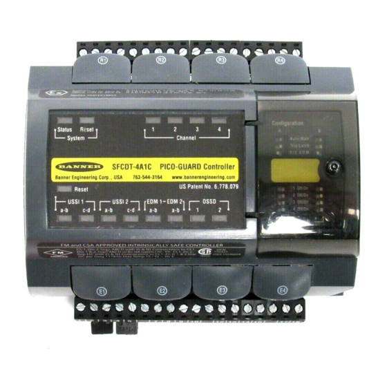
PICO-GUARD
Models SFCDT-4A1, SFCDT-4A1C
Section Contents
Section 1
System Overview . . . . . . . . . . . . . . . . . . . . . . . . . Page 1
Section 2
System Components and Specifications . . . . . . . Page 3
Section 3
Installation and Alignment . . . . . . . . . . . . . . . . . . Page 6
Section 4
System Operation . . . . . . . . . . . . . . . . . . . . . . . Page 18
Section 5
Troubleshooting and Maintenance . . . . . . . . . . . Page 28
Section 6
Periodic Checkout Procedures . . . . . . . . . . . . . . Page 32
9714 10th Avenue North • Minneapolis, MN 55441
Phone: 763.544.3164 • http://www.bannerengineering.com
Email: sensors@bannerengineering.com
™
04/04
Patent Pending
P/N 69761 rev. B
Advertisement
Table of Contents
Troubleshooting

Related Manuals for Banner PICO-GUARD SFCDT-4A1


Summary of Contents for Banner PICO-GUARD SFCDT-4A1
- Page 1 PICO-GUARD ™ Fiber Optic Safety System Controller Instruction Manual Models SFCDT-4A1, SFCDT-4A1C Section Contents Section 1 System Overview ......Page 1 Section 2 System Components and Specifications .
-
Page 2: Table Of Contents
2.3 Accessories ........4 that are beyond the control of Banner Engineering Corp. These factors 2.4 Replacement Parts . -
Page 3: System Overview
System Overview Instruction Manual 1. System Overview 1.1 Description The Banner PICO-GUARD fiber optic safety system is a MPCE or other load is required, an accessory interface module diverse-redundant microprocessor-controlled optoelectronic or redundant positive-guided contactors may be used to guarding system. This system consists of a controller, flexible... -
Page 4: Applications And Limitations
System Overview Instruction Manual The optical elements (such as fiber optic safety interlock Generally, use of the Banner PICO-GUARD System is not switches, points or grids) are available in a variety of allowed: configurations to allow easy installation and proper operation •... -
Page 5: System Components And Specifications
(11.5') PWS435P PWXP435P PWXT435P 2.2 Plastic Optical Fiber (13.1') PWS440P PWXP440P PWXT440P Plastic optical fiber for use with Banner PICO-GUARD PWS445P PWXP445P PWXT445P 4.5 m (14.7') optical elements is available in bulk form (to be cut to PWS450P PWXP450P PWXT450P (16.4') -
Page 6: Accessories
1 / 2 E D M 1 / 2 E D M 1 / 2 E D M SFCDT-4A1 S FCDT-4A1 PICO-GUARD Controlle r PICO-GUARD Controlle r Banner Engineering Corp., USA 763-544-3164 www.bannerengineering.com SFA-CMH Black PVC sheathing, 100' Reset 1 Off/O n... -
Page 7: Specifications
OSSDs to turn OFF (Trip condition). (See Section 3.7.) Two redundant solid-state 24V dc, 0.5A max. sourcing OSSD (Output Signal Switching Device) safety outputs. (Use optional interface modules for ac or larger dc loads.) Capable of the Banner “Safety Handshake” (see Section 1.1). OSSD Outputs ON-state voltage: ≥... - Page 8 OSSD (bi-color Red/Green): status of the OSSD outputs Config (bi-color Red/Green): status of the system configuration Model SFCDT-4A1 Model SFCDT-4A1C LISTED Certifications Presence Approvals pending Sensing Device 10Y8 Banner Engineering Corp. Minneapolis, U.S.A. • www.bannerengineering.com • Tel: 763.544.3164 P/N 69761 rev. B...
-
Page 9: Installation And Alignment
Read Section 1.2 and all of Section 3 of this manual carefully before installing the system. Failure to follow these instructions could result in serious bodily injury or death. Banner Engineering Corp. Minneapolis, U.S.A. • www.bannerengineering.com • Tel: 763.544.3164... -
Page 10: Security Protocol
Up to four remote display units may be connected to one controller. See installation instructions included with the remote display for more information. Banner Engineering Corp. Minneapolis, U.S.A. • www.bannerengineering.com • Tel: 763.544.3164 P/N 69761 rev. B... -
Page 11: Electrical Connections
Connect the system power wires to the +24V dc terminal (21) and the 0V dc terminal (20). 3.5 Optical Fiber Installation Use only the Banner fiber optic cable listed in Section 2, or call Banner factory applications department to determine fiber suitability. For best operation, minimize the fiber lengths, number of splices, number of tight bends and operating Figure 3-3. -
Page 12: Optical Element Installation
• Rope pull switches USSI Input • Mechanical safety interlock switches Terminals • Safety outputs from safety light screens (contacts or Banner “handshake”-compatible solid-state safety outputs) • Safety outputs from safety modules (contacts or Banner Figure 3-5. Multiple External Stop Device hookup “handshake”-compatible solid-state safety outputs) -
Page 13: Initial System Checkout
NOTE: For external stop devices with solid-state outputs, the Controller configuration is done at the two banks of DIP outputs must be Banner Engineering safety devices switches located under the clear access cover on the right side with “handshake” verification. Connect the compatible of the controller (see Figure 3-6). -
Page 14: Electrical Interface To Guarded Machine
OSSD outputs of the PICO-GUARD. FSDs can also be used to control an additional number of hazards by creating multiple safety stop circuits. Banner Engineering Corp. Minneapolis, U.S.A. • www.bannerengineering.com • Tel: 763.544.3164... - Page 15 When the OSSD outputs have changed from ON to OFF, EDM 1 input will be verified to be in the closed state within 250 ms. Banner Engineering Corp. Minneapolis, U.S.A. • www.bannerengineering.com • Tel: 763.544.3164...
-
Page 16: Preparing For System Operation
MPCE (or FSD) is wired as described in Section 3.9.3 and as shown in Figures 3-7, 3-8, 3-9, and 3-10. Banner Engineering Corp. Minneapolis, U.S.A. • www.bannerengineering.com • Tel: 763.544.3164... - Page 17 It is possible for the suppressors to fail as a short circuit. Figure 3-7. PICO-GUARD System generic FSD hookup; two-channel EDM Banner Engineering Corp. Minneapolis, U.S.A. • www.bannerengineering.com • Tel: 763.544.3164...
- Page 18 It is possible for the suppressors to fail as a short circuit. Figure 3-8. PICO-GUARD System interface module (IM-T-9A) hookup; two-channel EDM Banner Engineering Corp. Minneapolis, U.S.A. • www.bannerengineering.com • Tel: 763.544.3164...
- Page 19 It is possible for the suppressors to fail as a short circuit. Figure 3-9. PICO-GUARD System interface module (IM-T-9A) hookup; one-channel EDM Banner Engineering Corp. Minneapolis, U.S.A. • www.bannerengineering.com • Tel: 763.544.3164...
- Page 20 It is possible for the suppressors to fail as a short circuit. Figure 3-10. PICO-GUARD System generic FSD hookup; two-channel EDM and two PICO-GUARD Systems Banner Engineering Corp. Minneapolis, U.S.A. • www.bannerengineering.com • Tel: 763.544.3164...
-
Page 21: System Operation
Qualified Persons only. 1 Off/On Optical Channels 2 Off/On 3 Off/On 4 Off/On Channel Figure 4-2. PICO-GUARD controller configuration switches Figure 4-1. Accessing the controller’s configuration panel Banner Engineering Corp. Minneapolis, U.S.A. • www.bannerengineering.com • Tel: 763.544.3164 P/N 69761 rev. B... -
Page 22: Resetting The Controller
The controller will power up in one of two ways, depending on the Auto/Man configuration setting. If the controller is set for Auto Power-Up, it will power up and reset automatically; if Banner Engineering Corp. Minneapolis, U.S.A. • www.bannerengineering.com • Tel: 763.544.3164... - Page 23 1 / 2 E D M 1 / 2 E D M 1 / 2 E D M SFCDT-4A1 S FCDT-4A1 PICO-GUARD Controlle r PICO-GUARD Controlle r Banner Engineering Corp., USA 763-544-3164 www.bannerengineering.com Reset 1 Off/O n 1 Off/O n 1 Off/O n...
- Page 24 5. OFF unless OSSD fault, then Red Flashing 6. OFF unless EDM fault, then Red Flashing 7. 2-channel EDM: both indicators ON; 1-channel EDM: EDM 1 indicator ON only Banner Engineering Corp. Minneapolis, U.S.A. • www.bannerengineering.com • Tel: 763.544.3164 P/N 69761 rev. B...
- Page 25 11. Solid Green on channels that were not blocked since last reset 6. OFF unless EDM fault, then Red Flashing 12. Channels that have been interrupted and cleared again since last reset Banner Engineering Corp. Minneapolis, U.S.A. • www.bannerengineering.com • Tel: 763.544.3164...
- Page 26 (PES), such as a PLC, that a fault has been detected and a Lockout condition exists. See Section 2.7 for output specifications. Banner Engineering Corp. Minneapolis, U.S.A. • www.bannerengineering.com • Tel: 763.544.3164...
-
Page 27: Remote Interface
Figure 4-7 is available. Two data packet characters are used to decode each diagnostic data byte. Figure 4-5. A sample screen display of the diagnostic software program Banner Engineering Corp. Minneapolis, U.S.A. • www.bannerengineering.com • Tel: 763.544.3164... - Page 28 Channel 4 Channel 4 Channel Channel 4 Channels Enabled Clear Weak Noisy Enabled Clear 4 Weak Noisy 3 and 4 Reserved Reserved Figure 4-7. RS-232 diagnostic data Banner Engineering Corp. Minneapolis, U.S.A. • www.bannerengineering.com • Tel: 763.544.3164 P/N 69761 rev. B...
- Page 29 0: The system configuration is valid. 1: Two-Channel EDM selected. 0: One-Channel EDM bit = 1: One-Channel EDM selected. One-Channel EDM bit = 0: No EDM selected. Banner Engineering Corp. Minneapolis, U.S.A. • www.bannerengineering.com • Tel: 763.544.3164 P/N 69761 rev. B...
- Page 30 1: Channel 4 is Clear but has a weak signal. 0: Channel 4 is not weak (Clear/strong or Blocked). Channel 4 Noisy 1: Noise detected on Channel 4. 0: No noise detected on Channel 4. Banner Engineering Corp. Minneapolis, U.S.A. • www.bannerengineering.com • Tel: 763.544.3164 P/N 69761 rev. B...
-
Page 31: Troubleshooting And Maintenance
GUARD System wires from high-voltage wires. Electrical connections or repairs should be done only by a Qualified Person (see Section 3.2). Banner Engineering Corp. Minneapolis, U.S.A. • www.bannerengineering.com • Tel: 763.544.3164 P/N 69761 rev. B... - Page 32 Troubleshooting and Maintenance PICO-GUARD Controller Instruction Manual The Banner BT-1 Beam Tracker is a very good tool for Checking for sources of optical noise: Turn off the controller, detecting electrical noise. It can be used to detect electrical completely block the emitter beam, or disconnect the emitter transient spikes and surges.
- Page 33 • Excessive optical or EMI/RFI noise or EMI/RFI noise. *Error Code is not visible on controller. Obtain error codes via RS-232 interface to PC or other device. Figure 5-1. Error code troubleshooting (2 of 2) Banner Engineering Corp. Minneapolis, U.S.A. • www.bannerengineering.com • Tel: 763.544.3164...
-
Page 34: Troubleshooting Weak Signal (Low Excess Gain) Conditions
Design Guide.) the factory, please do the following: • Extra splices and/or attenuators. 1) Contact the Banner Factory Application Engineering group at 3. Ensure optimum optical alignment and operating distances the address or numbers listed below: between optical elements. Keep the operating distance as Banner Engineering Corp., Application Engineering Group... -
Page 35: Periodic Checkout Procedures
6. Periodic Checkout Procedures 6.3 Commissioning Checkout Study each procedure in its entirety, to be sure to understand Refer all questions to the Banner each step before beginning. Perform this checkout procedure as part of System installation Applications Engineering Department at the address or (after the System has been interfaced to the guarded machine numbers listed on the front cover of this manual. - Page 36 Upon closing (clearing) the beam, verify that the machine does not automatically restart, and that the initiation devices must be engaged to restart the machine. Banner Engineering Corp. Minneapolis, U.S.A. • www.bannerengineering.com • Tel: 763.544.3164 P/N 69761 rev. B...
-
Page 37: Daily Checkout Procedure
Section 3.9. If Daily Checkout cards are missing, copies are available 6) o Inspect the area near the optical elements (including by contacting Banner Engineering or download at www. guard frame pieces, work pieces and the guarded machine) bannerengineering.com. - Page 38 System Status indicator flashing Red dangerous machine motion when a person or object enters the Other indicators (indicating error type) may also flash Red beam. Serious bodily injury or death could result. Banner Engineering Corp. Minneapolis, U.S.A. • www.bannerengineering.com • Tel: 763.544.3164...
- Page 39 Attempts to use the guarded machine under such conditions is the same or less than the overall system response could result in serious bodily injury or death. time specified by the machine manufacturer. (Banner’s Applications Engineering Department can recommend a suitable instrument.) Banner Engineering Corp.
- Page 40 PICO-GUARD Controller Instruction Manual Banner Engineering Corp. Minneapolis, MN U.S.A. • www.bannerengineering.com • Tel: 763.544.3164 P/N 69761 rev. B...
- Page 41 PICO-GUARD Controller Instruction Manual Banner Engineering Corp. Minneapolis, U.S.A. • www.bannerengineering.com • Tel: 763.544.3164 P/N 69761 rev. B P/N 69761 rev. B...
- Page 42 PICO-GUARD Controller Instruction Manual Banner Engineering Corp. Minneapolis, MN U.S.A. • www.bannerengineering.com • Tel: 763.544.3164 P/N 69761 rev. B...
- Page 43 U.S. Application Standards SOURCES OSHA Documents ANSI B11.1 ANSI B11.16 Mechanical Power Presses Metal Powder Compacting Presses Superintendent of Documents ANSI B11.2 Hydraulic Power Presses Government Printing Office ANSI B11.17 Horizontal Extrusion ANSI B11.3 Power Press Brakes P.O. Box 371954 Presses ANSI B11.4 Shears...
- Page 44 This warranty does not cover damage or liability for the improper application of Banner products. This warranty is in lieu of any other warranty either expressed or implied.
Need help?
Do you have a question about the PICO-GUARD SFCDT-4A1 and is the answer not in the manual?
Questions and answers