Table of Contents
Advertisement
Quick Links
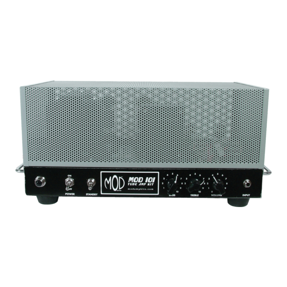
MOD 101 GUITAR AMP KIT (K-MOD101)
ON
OFF
POWER
1 5/
16"
Use these instructions to learn:
How to build a tube amp.
How to bias a tube amp for 6L6GC or EL34 power tubes.
Some modifications for altering the tone of a tube amp.
This tube guitar amplifier circuit is basic and classic. It can produce warm clean tone at low volume and
rich overdrive distortion at higher volume.
MOD 101
TUBE AMP KIT
STANDBY
5
5
4
6
4
3
7
3
2
8
2
1
9
1
0
10
0
BASS
TREBLE
1
Copyright © 2015 by modkitsdiy.com
5
6
4
6
7
3
7
8
2
8
9
1
9
10
0
10
VOLUME
INPUT
www.modkitsdiy.com
Advertisement
Table of Contents

Related Manuals for Mod 101

Summary of Contents for Mod 101
- Page 1 MOD 101 GUITAR AMP KIT (K-MOD101) MOD 101 TUBE AMP KIT POWER STANDBY BASS TREBLE VOLUME INPUT 1 5/ 16" Use these instructions to learn: How to build a tube amp. How to bias a tube amp for 6L6GC or EL34 power tubes.
-
Page 2: Table Of Contents
TABLE OF CONTENTS TOOL LIST …………………………………………………………………………...3 PARTS LIST …………………………………………………………………………...4 SAFETY …………………………………………………………………………...6 SOLDERING TIPS …………………………………………………………………...7 WIRING TIPS ……………………………………………........8 HARDWARE FASTENING TIP …………………………………………………...9 STEP BY STEP ASSEMBLY INSTRUCTIONS …………………………………...9 Section 1 – Mounting of Top Components …………………………………...9 Section 2 – Mounting of Front Components ………………………………….12 Section 3 –... -
Page 3: Tool List
MOD 101 GUITAR AMP KIT – BACKGROUND The MOD 101 Guitar Amp Kit was designed for anyone who is interested in building their own tube guitar amplifier head and learning some simple circuit modifications that can be used to tailor the sound to better suit their tonal preference. -
Page 4: Parts List
PARTS LIST Please see the parts list drawings for help with finding and identifying each part along with corresponding part numbers. CAPACITORS: RESISTORS: Description Quantity Description Quantity 250pF 500V 1Ω 1/2W 500pF 500V 1Ω .001µF 630V 47Ω 1/2W .022µF 630V 360Ω... - Page 5 MISCELLANEOUS PARTS: Description Quantity Solid state diode 1N4007 250kΩ audio pot 1MΩ audio pot 25kΩ linear pot Chicken head knob Impedance switch & output jack 9 pin miniature tube socket Octal tube socket Tube clip Rubber Grommet Strain Relief Input jack Purple jewel Power switch (DPDT) Standby switch (SPST)
-
Page 6: Safety
If you smell smoke, hear something pop, or the chassis becomes too hot to touch, turn off power and unplug immediately. SAFETY Tube amps operate at high voltages that have the potential to injure and kill. Please remember the following when working on this project. -
Page 7: Soldering Tips
SOLDERING TIPS It is important to make a good solder joint at each connection point. A cold solder joint is a connection that may look connected but is actually disconnected or intermittently connected. (A cold solder joint can keep your project from working.) Follow these tips to make a good solder joint. -
Page 8: Wiring Tips
WIRING TIPS There are two different gauges of stranded wire included with the kit. Use 22 AWG wire unless noted otherwise in the instructions. The lower AWG (American Wire Gauge) number signifies a thicker gauge of wire, which can handle more current. (It is important to use the thicker gauge wire where specified in the instructions.) Because of the electro-magnetic 20AWG... -
Page 9: Hardware Fastening Tip
HARDWARE FASTENING TIP When fastening components with mounting hardware (screws, lock washers, and hex nuts), the lock washer and hex nuts should be fastened on the other side of the chassis from the head of the screw in the order pictured below. - Page 10 Step 5 – Mount the 9 pin miniature tube sockets Drawing 3 shows where to mount the two 9 pin miniature sockets. Make sure that pins 1 & 9 face away from the rear edge of the chassis. (Use #4 hardware). Step 6 –...
- Page 11 Step 8 – Mount the Output Transformer Remove the 1650P output transformer from its packaging. Drawings 4 and 5 show where to mount the output transformer. A) Cut off the blu/yel and brn/yel wires as described on the drawing. B) Place the transformer on its side and push the wires (one at a time) through their respective grommet holes as indicated on the drawing.
-
Page 12: Section 2 - Mounting Of Front Components
Step 10 – Mount the Filter Cap Terminal Strips Drawing 6 shows where to mount the 5 terminal strips which will be used for mounting the filter capacitors. Use #6 hardware. Step 11 – Mount the Danger Label Drawing 6 shows where to mount the danger label. This sticker is mainly used to scare people away from the amp if you have the steel cage removed. -
Page 13: Section 3 - Mounting Of Rear Components
Step 4 – Mount the Bass, Treble, and Volume Pots Drawing 7 shows where to mount the bass, treble, and volume pots. When they are mounted, turn their shafts all the way counter-clockwise. (Once you have done this, you can mount the chicken head knobs while pointing to “0”... -
Page 14: Section 4 - Mounting Internal Terminal Strips And Passive Components
Step 3 – Mount the Fuse Holder Drawing 8 shows where to mount the Fuse holder. You can also insert the 2A slow blow fuse at this time. SECTION 4 – Mounting Internal Terminal Strips and Passive Components Please refer to Drawings 9 - 11. Step 1 –... - Page 15 T2 Components Resistors Capacitors 820Ω 1/2W 22µF (Copy the orientation of polarity used in the drawing). 68kΩ 1/2W T3 Components Capacitors Resistors .1µF 630V 20kΩ 1/2W T4 Components Resistors 100kΩ 82kΩ T5 Components Capacitors Resistors 6.8kΩ 1/2W .022µF 630V 68kΩ 1/2W 500pF 500V...
-
Page 16: Section 5 - Solder The Filter Components
Step 3 – Connect the Bias Check Resistors Drawing 11 shows where to connect these resistors. (These resistors will help us when biasing the power tubes at the end of the instructions). V3 Components Resistors 1Ω 1/2W One lead of this resistor must be connected to both V3 pins 8 and 1. The other lead must be connected to the locking lug nearby. (*Measure this resistor with your DMM and take note that it most likely does not measure exactly 1.0 Ω) V4 Components Resistors... - Page 17 Terminal 3 Terminal 2 Terminal 1 ground T12 Components Capacitors Resistors 22µF 500V 5kΩ Positive side of bottom cap is connected to terminal 1 1kΩ Positive side of top cap is connected to terminal 3 One end only of 1k connects to this terminal from T13 T13 Components Capacitors Resistors...
-
Page 18: Section 6 - Connect The Front Mounted Components
T13 Wires E will connect to T4. D will connect to T4. (Make sure this wire has enough (Make sure this wire has enough length to get to about an inch past T4). length to get to about an inch past T4). 4"... - Page 19 Throw Throw Step 2 – Connect the Power and Standby Switches Drawing 13 shows some of these connections. A) Connect the TR2 (red) to Pole B (do not solder this Pole Pole connection, yet). Throw Throw Throw Pole B) Connect the 1Ω, 5W resistor from Throw B Off to Standby Switch Power Switch the nearby locking lug.
-
Page 20: Section 7 - Connect Tr2 To The Impedance Selector Switch
C) Connect wire “V3 cathode” to V3 pin 1. D) Connect wire “D” to T4 terminal 2. Throw Throw E) Connect wire “E” to T4 terminal 5. Pole Pole Step 4 – Connect the Remaining Front Mount Components Throw Throw Drawing 15 shows these connections. - Page 21 B) Connect TR2 yellow wire to C2 and now solder the connection. Switch terminal name convention C) Connect TR2 grn/yel wire to A2. D) Connect TR2 blk/yel wire to B. blk/yet grn/yel E) Connect TR2 grn wire to A. F) Connect TR2 blk wire to B2.
-
Page 22: Section 8 - Connect The Tube Sockets
SECTION 8 – Connect the Tube Sockets Note: Terminals are numbered from left to right with mounting bracket Please refer to Drawing 18. directed towards the viewer. Step 1 – Connect V1 Drawing 18 shows these connections. A) Connect V1 pin 1 to T4 terminal 6. B) Connect V1 pin 2 to T2 terminal 3. -
Page 23: Section 9 - Connect The Terminal Strip Interconnects
SECTION 9 – Connect the Terminal Strip Interconnects Note: Terminals are numbered from Please refer to Drawing 19. left to right with mounting bracket directed towards the viewer. A) Connect T4 terminal 6 to T5 terminal 5. B) Connect T1 terminal 2 to T4 terminal 4. C) Connect T4 terminal 3 to T3 terminal 3. -
Page 24: Section 11 - Insert The Strain Relief And Connect The Power Cord
B) Twist and connect two 20AWG green wires from V3 pins 2 & 7 to V2 pins 4, 5 & 9. At V2 one wire connects to both pins 4 & 5, while the other wire only connects to pin 9. (Only solder the connection at V3). -
Page 25: Section 12 - Fasten The Rubber Feet To The Chassis Cover
Step 2 – Connect the Power Cord Wires Drawing 22 shows where to connect the wires. A) Connect the Power Cord black wire to T9 terminal 1 (now solder this connection). B) Connect the Power Cord green wire to T9 terminal 2. C) Connect the Power Cord white wire to T9 terminal 3 (now solder this connection). -
Page 26: Section 14 - Set The Bias Of The Power Tubes
SECTION 14 – Set the Bias of the Power Tubes Please refer to Drawings 23 - 25. You should insert all vacuum tubes into their respective sockets at this point. 6L6GC or EL34 6L6GC or EL34 12AT7/ 12AX7/ ECC81 ECC83 Step 1 –... - Page 27 C) Determine the bias range for your power tubes. 6L6GC’s EL34'S For 6L6GC you want to stay in the current For EL34 you want to stay in the current range range of 10 mA – 50 mA. of 10 mA – 75 mA. Ohm’s Law allows us to measure voltage across a Ohm’s Law allows us to measure voltage across a resistor and know how much current is flowing through...
-
Page 28: Section 15 - Fasten The Steel Cage To The Chassis Box
SECTION 15 – Fasten the Steel Cage to the Chassis Box Turn off and unplug the amp. Use the #8 self-tapping screws to fasten the cage on to the chassis box on both sides. (s.t (s.t #8 self-tap screws You will have to use a lot of force to initially insert the self tapping screws. -
Page 29: Section 16 - Modifications
Tone Stack Mod This mod allows you to change the tone stock for a vintage Fender style. It should add brightness and clarity to the overall tone. (Because this mod has the most components, we have supplied an extra terminal strip so that you can swap out tone stacks easier). - Page 30 Remove the 20K resistor from T3 and replace it with an 820. Resistors 820Ω 1/2W Bypass Cap Mod This Mod is very simple. Changing this capacitor should make the highs a little smoother. Remove the 25µF cap from T2 and replace it with a 220µF cap. Caps 220µF Power Tube Mod Change the power tubes to 6L6GC’s or EL34’s and re-bias the amp following section 14.
- Page 31 Drawing 1 REAR GROMMET 4 R(BIAS) GROMMET 2 GROMMET 1 GROMMET 3 GROMMET 5 FRONT...
- Page 32 Drawing 2 GROMMET 4 R(BIAS) GROMMET 2 COLD GROMMET 1 GROMMET 3 GROMMET 5 FRONT...
- Page 33 Drawing 3 REAR Pin 1 Pin 1 Pin 8 Pin 8 Pin 9 Pin 9 Pin 1 Pin 1 #6 Locking Lugs R(BIAS) GROMMET 2 25KL GROMMET 4 COLD GROMMET 1 GROMMET 3 GROMMET 5 Mount the bias pot with solder lugs directed towards the front.
- Page 34 Drawing 4 R(BIAS) Secondary 1. Yel GROMMET 2 2. Grn/Yel GROMMET 4 3. Blk/Yel 4. Grn 5. Blk COLD GROMMET 1 GROMMET 3 Primary 1. Blu 2. Red 3. Brn GROMMET 5 Pull the wire out as far as possible 1.
- Page 35 Drawing 5 R(BIAS) GROMMET 1 GROMMET 2 Secondary 1. Grn Primary 2. Grn 1. Blu 3. Grn/Yel 2. Blk 4. Red 3. Brn 5. Red 4. Wht 6. Red/Yel COLD 7. Vio 1. Blu/Yel 2. Wht/Blk 1. Yel 3. Blk/Red 1650P 2.
- Page 36 Drawing 6 R(BIAS) COLD 1650P #6 Locking Lugs with slit cut HIGH VOLTAGE DANGER MAY BE PRESENT ON FILTER CAPACITORS DO NOT TOUCH! FRONT...
- Page 37 Drawing 7 MOD 101 TUBE AMP KIT BASS TREBLE VOLUME INPUT POWER STANDBY 250KA 250KA Remove all 6 screws from the terminals. You will not need them for this project. MOD 101 TUBE AMP KIT BASS TREBLE VOLUME INPUT POWER...
- Page 38 Drawing 8 IMPEDANCE (Ω) OUTPUT TO ≈120VAC SPEAKER(S) SELECTOR SLO BLO 60Hz Leave this strain relief hole open for now. IMPEDANCE (Ω) OUTPUT TO ≈120VAC SPEAKER(S) SELECTOR SLO BLO 60Hz...
- Page 39 Drawing 9 FRONT Primary 1. Blu 2. Red 3. Brn Secondary 1. Grn Primary 2. Grn 1. Blu 3. Grn/Yel 2. Blk 4. Red 3. Brn 5. Red 4. Wht 6. Red/Yel 7. Vio R(BIAS) Secondary 1. Yel 2. Grn/Yel 3.
- Page 40 Drawing 10 FRONT Primary 1. Blu 2. Red 3. Brn Secondary 1. Grn Primary 2. Grn 1. Blu 3. Grn/Yel 2. Blk 4. Red R(BIAS) 3. Brn 5. Red 4. Wht 6. Red/Yel 7. Vio Secondary 1. Yel 2. Grn/Yel 3.
- Page 41 Drawing 11 FRONT Primary 1. Blu .022µF 2. Red .022µF 3. Brn 630V 630V 500V 6.8K 100K 100K 100K 2.7K 1N4007 1N4007 2.4K It is important to copy the orientation of polarity Secondary shown for each of the 1. Grn Primary three diodes.
- Page 42 Drawing 12 ABOVE VIEW SIDE VIEW 80µF 450V 220K 220K 80µF 450V J1 & J2 Terminal 3 cathode 220K Terminal 2 Terminal 1 ground 22µF 500V cathode 22µF 500V 220K 4.7K 22µF 500V 4.7K HIGH VOLTAGE DANGER MAY BE PRESENT ON FILTER CAPACITORS DO NOT TOUCH! 22µF 500V...
- Page 43 Drawing 13 Tie, but do not solder these connections yet. FRONT BASS TREBLE VOLUME CHASSIS TOP (INSIDE VIEW) WITH COMPONENT NAMES (3) STEP 1 STEP 2 SIDE SIDE 10W 360Ω Primary 1. Blu .022µF 2. Red .022µF 630V 3. Brn 630V 500V 6.8K...
- Page 44 Drawing 14 Be careful not to confuse the sub-step letters on this drawing with the wire names. For example, the first part of Step 3 on page 19 is sub-step (A) and involves twisting wires “B” and “HV” together. “B” “HV”...
- Page 45 Drawing 15 BASS TREBLE VOLUME FRONT CHASSIS TOP (INSIDE VIEW) WITH COMPONENT NAMES (3) Keep the body of this resistor from leaning against the nearby wires. .022µF .022µF 630V 630V 500V 20 AWG 6.8K Wire 100K 100K 100K 2.7K Primary 1.
- Page 46 Drawing 16 REAR Tie, but do not solder these Blk & Blu connections yet. Secondary 1. Yel 2. Grn/Yel 3. Blk/Yel 4. Grn .001µF 5. Blk 630V Tie, but do not solder these connections yet. 1.5K 220K 220K 1.5K Secondary R(BIAS) 1.
- Page 47 Drawing 17 blk/yel REAR grn/yel Tie, but do not solder these connections yet. Secondary 1. Yel 2. Grn/Yel 3. Blk/Yel 4. Grn .001µF 5. Blk 630V Tie, but do not solder these connections yet. 1.5K 220K 220K 1.5K Secondary R(BIAS) 1.
- Page 48 Drawing 18 blk/yel REAR grn/yel Tie, but do not solder these connections yet. .001µF 630V Tie, but do not solder these connections yet. 1.5K 220K 220K 1.5K R(BIAS) 2.4K 1N4007 1N4007 2.7K 100K 100K 100K 6.8K .022µF .022µF 500V 630V 630V...
- Page 49 Drawing 19 blk/yel REAR grn/yel Tie, but do not solder these connections yet. .001µF 630V Tie, but do not solder these connections yet. 1.5K 220K 220K 1.5K R(BIAS) 2.4K 1N4007 1N4007 2.7K 100K 100K 100K 6.8K .022µF .022µF 500V 630V 630V...
- Page 50 Drawing 20 REAR 20 AWG 20 AWG 20 AWG Wire Wire Wire .001µF 630V Tie, but do not solder these connections yet. 1.5K 220K 220K 1.5K R(BIAS) 2.4K 1N4007 1N4007 2.7K 100K 100K 100K 6.8K .022µF .022µF 500V 630V 630V...
- Page 51 Drawing 21 You will have to squeeze very tightly with the pliers to fit the strain relief and power cord into the chassis hole. This is what gives the cord a secure fit. Channellock Pliers 1"...
- Page 52 Drawing 22 REAR Black Green White .001µF 630V 1.5K 220K 220K 1.5K Brn & Wht R(BIAS) 2.4K 1N4007 1N4007 2.7K 100K 100K 100K 6.8K .022µF .022µF 500V 630V 630V...
- Page 53 Drawing 23 12AX7/ ECC83 22µF 500V 22µF 500V 22µF 500V 22µF 500V 12AT7/ ECC81 80µF 450V Ω 01.6 Ω WARNING: Do not measure resistance with amplifier power on. Start with pot turned R(BIAS) all the way to cold. 374BX POWER STANDBY UNPLUGGED...
- Page 54 Drawing 24 12AX7/ ECC83 OHM’S LAW 22µF 500V 22µF 500V OHM’S LAW 22µF 500V 22µF 500V 12AT7/ ECC81 6L6GC bias range: 10 mA – 50 mA (35 mA is used commonly) Apply Ohm’s Law to find the corresponding mV reading for your resistor value: 80µF 450V I = 35 mA BASS...
- Page 55 Drawing 25 12AX7/ ECC83 OHM’S LAW 22µF 500V 22µF 500V OHM’S LAW 22µF 500V 22µF 500V 12AT7/ ECC81 EL34 bias range: 10 mA – 75 mA (35 mA is used commonly) Apply Ohm’s Law to find the corresponding mV reading for your resistor value: 80µF 450V I = 48 mA BASS...
- Page 56 Parts List 1 R-A1 1Ω, ½W resistor BAG 6 R-A2D4K 2.4kΩ, ½W resistor R-B82K 82kΩ, 1W resistor brown 2.4K BAG 6 BAG 6 black gold gold grey yellow orange R-Q1 1Ω, 5W resistor gold gold BAG 7 R-A2D7K 2.7kΩ, ½W resistor R-A100K 100kΩ, ½W resistor 5W 1Ω...
- Page 57 Parts List 2 P-0401H 4 lug terminal strip (2 lug common) C-MD001-630 0.001µF capacitor S-HS832-34 #8 screw BAG 1 .001µF BAG 2 630V BAG 10 T2, T6 S-HST8-12 #8 self-tap screws C-MD022-630 0.022µF capacitor BAG 1 P-0500H 5 lug terminal strip (no common lugs) .022µF 630V S-HHN832...
- Page 58 Parts List 3 T-12AX7-S-JJ 12AX7/ECC83 preamp tube S-H142 tube clip R-V38-25KL 25kΩ potentiometer (linear taper) BAG 5 BAG 4 wiper BAG 3 wiper cold cold T-12AT7-JJ 12AT7/ECC81 preamp tube P-K300 black chicken head knobs P-G005 rubber grommet BAG 4 T-6L6GC-JJ-MP matched pair of 6L6GC power tubes BAG 4 P-H1200...
- Page 59 P-H495 standby switch (SPST) Parts List 4 BAG 5 K-PMOD101LABELS Labels P-H9107 rubber feet BAG 5 F-ZS020 fuse (2A Slow Blow) BAG 4 S-W126 power cord CARDBOARD TUBE S-H201 fuse holder BAG 4 S-W707L 10 ft of 20 AWG wire (green) BAG 5 K-P101-CHASSIS steel chassis box and cover...
- Page 60 (K-MOD101) TROUBLESHOOTING SUPPLEMENT With 6L6GC’s installed, use this supplement to help: Measure voltage test points to identify major discrepancies and locate problem areas. (Keep in mind that the voltage measurements will vary slightly from amp to amp. The voltages you measure should be in the same ballpark, but do not expect to get the exact same value.) www.modkitsdiy.com Copyright ©...
- Page 61 SAFETY Tube amps operate at high voltages that have the potential to injure and kill. Please remember the following when troubleshooting this project. Only work on the amp when you are wide awake and sober. Do not plug the amp in until you have gone through all of the instructions, checking and re-checking each step.
- Page 62 Test Point DC Voltage AC Voltage Voltages measured from test point to ground “HV” 521 VDC 2 VAC with no signal, bias pot turned all the way to cold and the following front panel “B” 492 VDC 0 VAC settings: “C”...
- Page 63 FILTER SECTION (INSIDE) Test Point DC Voltage AC Voltage Voltages measured from test point to ground “HV” 521 VDC 2 VAC with no signal, bias pot turned all the way to cold and the following front panel “B” 492 VDC 0 VAC settings: “C”...
- Page 64 POWER TUBE BIAS SUPPLY See Assembly Drawing 22 1.5K 220K 220K 1.5K -48 VDC 0 VAC R(BIAS) -4.17 VDC 0 VAC -48 VDC 2.4K 1N4007 0 VAC 1N4007 2.7K -280 mVDC 52.7 VAC 519 VDC 3 VAC 4.3 VDC 47.3 VAC Voltages measured from test point to ground with no signal, bias pot turned all the way to cold and the following front panel...
- Page 65 PREAMP TUBE ELECTRODES See Assembly Drawing 22 Voltages measured from test point to ground with no signal, bias pot turned all the way to cold and the following front panel settings: POWER: STANDBY: (UP POSITION) BASS: “0” TREBLE: “0” VOLUME: “0”...
- Page 66 POWER SWITCH FUNCTIONALITY / CONTINUITY CHECK Throw Throw Measure continuity with the amplifier unplugged. Pole Pole Throw Throw UNPLUG See Assembly Drawing 15 Switch Position Measure Between Continuity? Throw Throw Pole A and Throw A Off Pole A and Throw A On Pole Pole Pole B and Throw B Off...
- Page 67 100K 500p 100K INPUT 1.5K IMPEDANCE 250KA SELECTOR .1µ GRN/YEL BLU/YEL 220K TREBLE .022µ .001µ OUTPUT BIAS BLK/YEL 250KA BASS .022µ 100K BRN/YEL 220K 6.8K .1µ .1µ 1.5K 1N4007 R(BIAS) 25KL 2.7K 22µ 2.4K 22µ 4.7K 1N4007 STANDBY BLU/YEL POLE RED/YEL THROW SLO BLO...
- Page 68 483 VDC 100K 470 VDC 500p 100K INPUT 1.5K 276 VDC IMPEDANCE 250KA SELECTOR .1µ GRN/YEL BLU/YEL 68 VDC 0 VDC TREBLE 220K .022µ 35 mVDC .001µ 0 VAC OUTPUT BIAS BLK/YEL 250KA BASS .022µ 100K BRN/YEL 220K 36 mVDC 73 VDC 6.8K .1µ...
Need help?
Do you have a question about the 101 and is the answer not in the manual?
Questions and answers