Advertisement
Table of Contents
- 1 General Information
- 2 Hardware List
- 3 Parts Listing
- 4 Exploded Diagram
- 5 Wire Connections
- 6 Center Post Assembly
- 7 Foot Pedal Assembly
- 8 Monitor Assembly
- 9 Seat Frame Assembly
- 10 Safety and Maintenance
- 11 About Display
- 12 Operating Ranges
- 13 Things You Should Know before Exercising
- 14 Troubleshooting
- 15 Proof of Purchase
- Download this manual
Advertisement
Table of Contents

Related Manuals for Body Champ BRT3858


Summary of Contents for Body Champ BRT3858
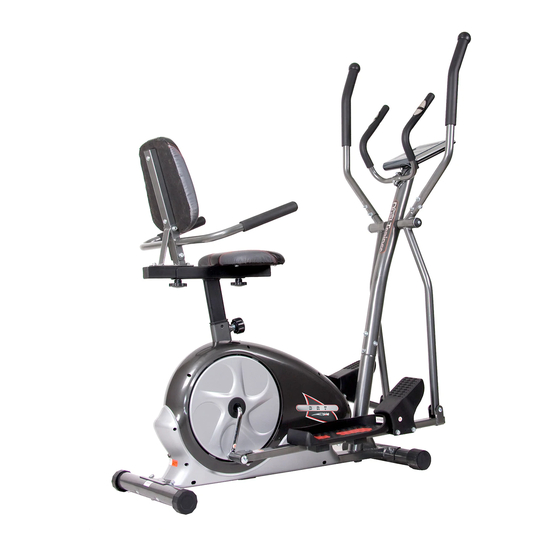
- Page 1 3-in-1 Trio Trainer U.S. Patent US9474925B1 BRT3858 * This item is for consumer use only and it is not meant for commercial use. * This item is for consumer use only and it is not meant for commercial use. OWN ER ’S MANUAL...
- Page 2 PLEASE KEEP THESE INSTRUCTIONS FOR FUTURE USE & REFERENCE. DO NOT DISCARD. WARNING: SERIOUS INJURIES AND EVEN DEATH CAN OCCUR IF THE PROPER SAFETY PRECAUTIONS ARE NOT FOLLOWED. The diagram below highlights and reviews many of the important Safety and Warning labels also found on the unit.
-
Page 3: General Information
General Information Safety Storage and Use Before you undertake any exercise program, Your product is intended for use in clean please be sure to consult with your doctor. dry conditions. You should avoid storage in Frequent strenuous exercise should be excessively cold or damp places as this may approved by your doctor and proper use lead to corrosion and other related problems. -
Page 4: Hardware List
Hardware List The following hardware is used to assemble your unit. Please take a moment to familiarize yourself with these items. Please note, most of these parts are already pre-assembled on your unit. Do not be alarmed if you see parts on this page that are not included in your hardware packet. -
Page 5: Parts Listing
Parts Listing The following parts list describes all of the parts illustrated on the exploded diagram on the following page. Please note, most of these parts are already pre-assembled on your unit. Part# Description Part# Description Main Frame Arc Washer (M6) Center Post Spring Washer (M8) Left Pedal Tube... -
Page 6: Exploded Diagram
Exploded Diagram The following diagram is provided to help you familiarize yourself with the parts and hardware that will be used during the assembly process. Please note that not all of the parts and hardware you see here will be used while you are assembling the machine because some of these items are already pre-installed. - Page 7 Assembly Instructions A s s e m b l y S t e p 1 Hardware Required FRONT STABILIZER ASSEMBLY BOLTS Using the drawing below for reference, secure the Front Stabilizer (#15) to the Main Frame (#01) using two Carriage Bolts (#20) followed by two Arc #20.
-
Page 8: Wire Connections
Assembly Instructions A s s e m b l y S t e p 2 Hardware Required WIRE CONNECTIONS BOLTS Connect the Main Sensor Wire (Lower)(#54A) to the Main Sensor Wire (Upper) (#53A). #31. Bolt (M8x15 mm) [6 Pieces] CENTER POST ASSEMBLY Remove the Bolts (#31), Spring Washers (#43),and WASHERS Arc Washers (#41) that are pre-assembled on the... - Page 9 Assembly Instructions A s s e m b l y S t e p 3 Hardware Required COUPLER BAR ASSEMBLY (Part I) BOLTS Referring to the diagram below, on the right side of the Center Post (#02) –in the following order--slide on one Plastic Bushing (#63), one Special Washer (#46) followed by the Right Coupler Bar (#06), one D Shape Washer (#45), one Round Cap (#64), one Washer (#40), and secure using one Bolt (#30).
-
Page 10: Foot Pedal Assembly
Assembly Instructions A s s e m b l y S t e p 4 Hardware Required PEDAL ASSEMBLY BOLTS Attach the Left/Right Pedals (#56/#57) onto the Left/Right Pedal Tubes (#03A/#04A) as shown in the drawing below using a total of three Hex Bolts (#28), #24.Hex Bolt (M8x105 mm) [4 Pieces] secured by three Washers (#40), and three Nylon Nuts (#38). - Page 11 Assembly Instructions A s s e m b l y S t e p 5 Hardware Required BOLTS HANDLE BAR ASSEMBLY Please remove the two Bolts (#31), two Spring Washers (#43), two Arc Washers (#41) pre-assembled on Left Coupler Bar (#05) and Right Coupler Bar (#06). #21.
-
Page 12: Monitor Assembly
Assembly Instructions A s s e m b l y S t e p 6 Hardware Required MONITOR ASSEMBLY BOLTS Remove the four Screws (#32) that are pre-assembled on the back of the . Set them aside #32. Screw (M5x12 mm) nearby as they will be used later in this process. -
Page 13: Seat Frame Assembly
Assembly Instructions A s s e m b l y S t e p 7 Hardware Required BOLTS SEAT FRAME ASSEMBLY With the help of an assistant, loosen the pre-assembled Spring Loaded Knob (#49) and pull back slightly on it so that you may proceed to insert the Seat Post (#09) into the mouth of the post that #25. - Page 14 Assembly Instructions A s s e m b l y S t e p 8 Hardware Required CUSHION ASSEMBLY BOLTS First, attach the Seat Cushion (#79) to the horizontal bar of the Seat Cushion Frame (#07) and secure from the bottom using four Bolts (#31). #26.
- Page 15 Assembly Instructions A s s e m b l y S t e p 9 Plug in the Adapter (#55A) male plug into the female socket located at the rear end of the unit. The assembly process is now complete. However, for your own safety, please make sure to read this entire Owner’s Manual which includes safety instructions and warnings, as well as any safety/warning labels affixed to the product before use.
-
Page 16: Safety And Maintenance
Safety & Maintenance SAFETY & WARNINGS • Make sure all nuts, bolts, and screws are tightened prior to use. • Be sure that all adjustment locking devices and safety devices are properly engaged prior to use! • Never over-tighten the above-mentioned devices and parts to avoid damage to the unit. •... - Page 17 Computer Operation The monitor is designed for programmable magnetic bikes and introduced with the following categories: - Key Functions - About Display - Operating Ranges - Things You Should Know Before Exercising - Operation Instructions FUNCTION KEYS (on the surface of the fitness monitor) There are total 6 keys including START/STOP, ENTER, MODE, UP, DOWN, and TEST ( RECOVERY).
-
Page 18: About Display
Computer Operation ABOUT DISPLAY START: Indicate the selected program has started. STOP: Indicate the selected program has stopped. And, users are free to change the programs and the value of functions applied. PROGRAMI n n d : icate the selected programs from PROGRAM 1 to PROGRAM 17. LEVEL n: Indicate the selected level of loading from LEVEL 1 to LEVEL 24. -
Page 19: Operating Ranges
Computer Operation OPERATING RANGES Value Range (Count Up) Count Down Preset Increment (Decrement) PROGRAM 1~17 17~1 LEVEL 1~24 24~1 GENDER Male/Female Male Manual PRO 99:00~1:00 TIME 0:00~99:59 0:00 1:00 Other PRO 99:00~5:00 (in) HEIGHT 40~100 100~40 Value Range (Count Up) Count Down Preset Increment (Decrement) - Page 20 Computer Operation Body Types: There are 4 body types divided according to the FAT% calculated. Type Woman Type 1 (FAT=0.0%~13.0%) (FAT=0.0%~23.0%) Type 2 (FAT=13.1%~25.8%) (FAT=23.1%~35.8%) Type 3 (FAT=25.9%~30.0%) (FAT=35.9%~40.0%) Type 4 (FAT=30.1%~50.0%) (FAT=40.1%~50.0%) 6. BMR: Basal Metabolic Rate 7. BMI: Body Mass Index OPERATION INSTRUCTIONS Exercising with specific goal: •...
- Page 21 Computer Operation Body Fat Program: Program is a special program designed to calculate users' body fat ratio and to design a specific loading profile for users. With 4 different body types, the computer can generate 4 different profiles for each. Press “ENTER” key to select GENDER, HEIGHT WEIGHT, and AGE.
-
Page 22: Troubleshooting
Troubleshooting (AFTER COMPLETE ASSEMBLY) Solution Troubleshoot Area If the computer is not picking up your hand pulse signal (or you are getting HAND PULSE SIGNAL inaccurate readings), please adjust the following: Slightly moisten/dampen the palms with water so the sensors can detect a pulse signal. - Page 23 Warm-Up Instructions Before use, you must read and understand all instructions & warning stated in this Owner's Manual as well as posted on the equipment. The following flexibility exercises are provided to you as a means to prevent injury while you are exercising. A proper warm-up routine decreases the chance of injuring your muscles while you are exercising.
- Page 24 Warm-Up Instructions Trunk Flexion, Prone 1. Assume the depicted position on your hands and knees. Stretch your hands out in front of you and then slowly start to pull them back in toward your body as you tuck your chin and arch your back upward. 2.
-
Page 25: Proof Of Purchase
Proof of purchase Model Number BRT 3858 version:04-12-2019... - Page 26 This page intentionally left blank...
- Page 27 This page intentionally left blank...
- Page 28 Body Flex Sports, Inc. • 21717 Ferrero Parkway, Walnut, CA 91789 • Telephone: (888) 266 - 6789 • Email: info@bodyflexsports.com Made In China...
Need help?
Do you have a question about the BRT3858 and is the answer not in the manual?
Questions and answers
Monitor replacement and price for a body champ 3 in 1 model b r t 3858
The monitor replacement for the Body Champ model BRT3858 is compatible with the T POWER 9V Charger used for Body Champ Cardio Dual Trainer Computer Monitors, including model BRT3858.
This answer is automatically generated
Looking for a monitor for a brt3858 body champ 3 in 1 where to purchase?
The Body Champ BRT3858 3-in-1 Trio-Trainer includes an advanced computer interface with a monitor as part of the machine. It features 17+ training programs, magnetic adjustable resistance with motor drive, and an integrated hand pulse heart rate monitor. Therefore, the monitor is already included with the equipment.
This answer is automatically generated
I would like to order parts for the brt 3858 part number 37 ( right foot pedal )
@Doug Hinson