
Related Manuals for Body Champ TRIO-TRAINER BRT7989


Summary of Contents for Body Champ TRIO-TRAINER BRT7989
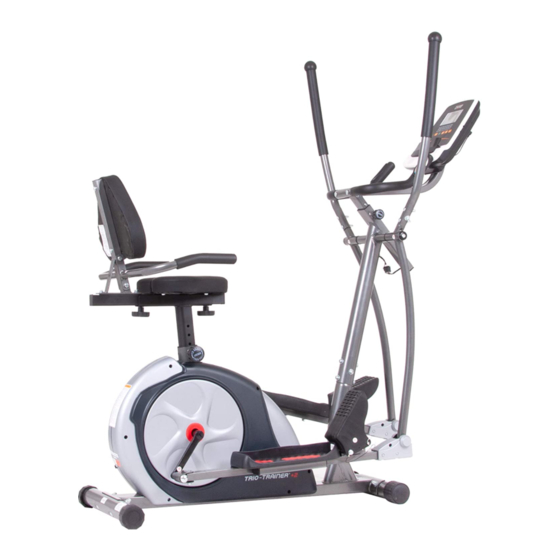
- Page 1 BRT7989/BRT7200 U.S. Patent number US9474925B1 This product is intended for indoor, home use only and is not to be used in a commercial setting. OWNER’S MANUAL...
- Page 2 PLEASE KEEP THESE INSTRUCTIONS FOR FUTURE USE & REFERENCE. DO NOT DISCARD. WARNING: SERIOUS INJURIES AND EVEN DEATH CAN OCCUR IF THE PROPER SAFETY PRECAUTIONS ARE NOT FOLLOWED. The diagram below highlights and reviews many of the important Safety and Warning labels also found on the unit. Please ensure any user of the unit familiarizes themselves with this Safety and Warning guidelines before use.
-
Page 3: General Information
General Information Safety Storage and Use Before you undertake any exercise program, please be sure to Your product is intended for use in clean dry conditions. You consult with your doctor. should avoid storage in excessively cold or damp places as Frequent strenuous exercise should be approved by your this may lead to corrosion and other related problems. -
Page 4: Before Assembly
Before Assembly WARNING 1. Take a few minutes to familiarize yourself with the parts and hardware included with your product. 2. The assembly may require two people. 3. Check the frame for any damage and check any wiring (if present) for rips or tears. If you detect damage, rips, or tears, please contact our Customer Support Team before beginning any assembly. -
Page 5: Part Listing
Part Listing The following parts list describes all of the parts illustrated in the exploded diagram on the following page. PLEASE NOTE: most of these parts are already pre-assembled on your unit. # Description # Description Main Frame Spring Washer (M8) Center Post Spring Washer (M6) Left Pedal Tube... -
Page 6: Exploded View
Exploded View The following diagram is provided to help you familiarize yourself with the parts and hardware that will be used during the assembly process. PLEASE NOTE : : Not all of the parts and hardware you see here will be used while you are assembling the machine because some of these items are already pre-installed. -
Page 7: Hardware And Tool List
Hardware and Tool List The following hardware is used to assemble your unit. Please take a moment to familiarize yourself with these items. PLEASE NOTE: Most of these parts are already pre-assembled on your unit. Do not be alarmed if you see parts on this page that are not included in your hardware packet. -
Page 8: Assembly Step
Assembly STEP 1 Hardware Required NOTE BEFORE STARTING THE ASSEMBLY PROCESS : To avoid misalignment due to over-tightening, please do not use a wrench and use only hand-tightening for now to ensure easy assembly. Wrench-tightening should be performed after all parts are assembled to ensure all nuts, bolts, and parts are tightly secured before use. -
Page 9: Wire Connections
Assembly STEP 2 WIRE CONNECTIONS Hardware Required Connect the Main Sensor Wire (Lower)(#88) to the Main Sensor Wire (Middle)(#87). CENTER POST ASSEMBLY #32 Bolt (M8 x 15mm) Remove the Bolts (32), Spring Washers (#47) and Arc [6 pieces] Washers (#49) that are pre-assembled on the Center Post (#02) and set them aside as they will be used in a later process. - Page 10 Assembly STEP 3 COUPLER BAR ASSEMBLY (Part I) Hardware Required Referring to the drawing below, insert the Axle (#19) through the horizontal stems on the Center Post (#02). Then, on the left side of the Axle (#19) -- in the following order, slide one Wavy Washer (#54) followed by the Left Coupler Bar (#05), one D Shape Washer (#53), one Round Cap (#76), one Washer (#52), and secure using one Bolt (#31).
- Page 11 Assembly STEP 4 COUPLER BAR ASSEMBLY (PART II) Hardware Required Attach the Right Pedal Tube (#04) onto the Crank (#21) as illustrated and secure by inserting from the outer edge of the Right Pedal Tube (#04), one Pedal Hinge Bolt (#28) and one Wavy Washer (#55).
-
Page 12: Foot Pedal Assembly
Assembly STEP 5 PEDAL ASSEMBLY Hardware Required Attach the Left/Right Pedals (#57/#58) onto the Left/Right Pedal Tubes (#03/#04) as shown in the drawing below using a total of six Hex Bolts (#36), six Washers (#52), and six Nylon Nuts (#46). #33 Hex Bolt (M8 x 105mm) FOOT PEDAL ASSEMBLY [2 pieces]... - Page 13 Assembly STEP 6 Hardware Required #26 Carriage Bolt (M8 x 45mm) [2 pieces] #49 Arc Washer (M8) #94 Screw (M5 x 10mm) [2 pieces] [1 piece] #39 Screw (M4 x 12mm) #41 Washer (M6) [4 pieces] [4 pieces] #46 Nylon Nut (M8) #92 Wire Cap [2 pieces] [2 pieces]...
-
Page 14: Monitor Assembly
Assembly STEP 6 (Cont.) Assembly STEP 6 MONITOR FRAME ASSEMBLY Pull the Main Sensor Wire (Upper) (#86) into the Monitor Frame (#12) as illustration 1. Loosen the Spring Loaded Knob (#23) and pull back slightly on it so that you may proceed to insert the Monitor Frame (#12) into the open- ing of the post that is protruding from the Center Post (#02). -
Page 15: Handle Bar Assembly
Assembly STEP 7 HANDLE BAR ASSEMBLY Hardware Required On the left side, insert Left Handle Bar (#14) into the opening at the tip of Left Coupler Bar (#05). Align the holes of the Left Handle Bar (#14) and Left Coupler Bar (#05) and secure from the side using one Bolt (#32), one Spring Washer (#47) and one Arc Washer (#49). -
Page 16: Seat Frame Assembly
Assembly STEP 8 SEAT FRAME ASSEMBLY Hardware Required Attach the Spring Loaded Knob (#22) to the Main Frame (#01). Loosen the Spring Loaded Knob (#22) and pull back slightly on it so that you may proceed to insert the Seat Post (#07) into the opening of the post that is protruding from the Main Frame (#01) #34 Hex Bolt (M8 x 60mm) down a minimum of four inches so that the corresponding holes can... - Page 17 Assembly STEP 9 SEAT CUSHION ASSEMBLY Hardware Required Attach the Seat Cushion (#80) to the Seat Cushion Frame (#08) and secure from the bottom using four Bolts (#32). BACKREST CUSHION ASSEMBLY Attach the Backrest Cushion (#81) to the Backrest Cushion #30 Bolt (M8 x 45mm) Frame (#09) and secure using two Bolts (#30) through [2 pieces]...
-
Page 18: Adapter Assembly
Assembly STEP 10 ADAPTER ASSEMBLY Hardware Required Plug in the Adapter (#83) male plug into the female socket located at the rear end of the shroud and then plug in the Adapter (#83) to the electrical outlet to start your workout. No Hardware Required NOTE : Please wrench-tightened all parts now that assembly is completed to... -
Page 19: Computer Operation
Computer Operation Function 1.Program: 21 programs as following A: 1 Manual Program (See fig 1) LEVEL ST OP TIME DIST. WATT fig 1 B: 10 Preset Program Profile: (See fig 2~fig 11) LEVEL ST OP LEVEL ST OP LEVEL ST OP TIME DIST. - Page 20 Computer Operation E: 4 User Setting Programs: CUSTOM1 to CUSTOM4 (See fig 17 ~ fig 20) LEVEL ST OP LEVEL ST OP LEVEL ST OP LEVEL ST OP TIME DIST. WATT TIME DIST. WATT TIME DIST. WATT TIME DIST. WATT fig 17 fig 18 fig 19...
- Page 21 Computer Operation 5. PULSE RECOVERY: ● First test your current heart rate and show your heart rate value, press this button to enter into pulse recovery testing. ● When you are in pulse recovery mode, press this button to exit. 6.
- Page 22 Computer Operation F. Press START/ STOP to begin exercise.(See fig 29) ● Watt Control Program A. Press(or rotate) UP, DOWN to select the watt control program. B. Press ENTER to confirm the selected watt control program and enter into time setting window. C.
- Page 23 Computer Operation ● HEART RATE CONTROL PROGRAM: TARGET HEART RATE The user can set any target heart rate to do the exercise. A. Press(or rotate) UP, DOWN button to select TARGET HEART RATE program. B. Press ENTER to confirm your choice and enter time setting window. C.
- Page 24 Computer Operation E. The age display will flash, and then press(or rotate) UP, DOWN button to set up your age. Press ENTER to confirm the value.(See fig 37) F. The gender display will flash, and then press(or rotate) UP, DOWN button to set up your gender. Press ENTER to confirm.(See fig 38) YE AR ST OP...
- Page 25 Computer Operation 3. Pulse Recovery Test The pulse recovery test is to compare your heart rate before and after exercise. It is target to determine your heart strength via the measuring. Please do the test as below: A. Both your hands hold the pulse sensor or via wireless transmitter belt to test the pulse(if applicable), the computer will display your current pulse value.
- Page 26 Computer Operation Display Error 1. When the computer displays ERROR1, please check if the motor is good and if the motor wires connect well. 2. When the computer displays ERROR2, please check if your hands contact the sensors well as there no body fat signal detected. Adaptor INPUT: AC220V (The voltage depends on different country)
-
Page 27: Troubleshooting
Troubleshooting (AFTER COMPLETE ASSEMBLY) Troubleshoot Area Solution Calories/Distance/ If the computer is not displaying the CALORIES/DISTANCE/TIME/(ETC.) functions (or you are getting inaccurate readings), please adjust Time (Etc.) the following: Check to ensure all computer sensor wires are properly connected and are not damaged. You may need to refer to installation/assembly directions for the sensor wires in this manual. -
Page 28: Safety And Maintenance
Safety and Maintenance Safety & Warning • Make sure all nuts, bolts, and screws are tightened prior to use. • Be sure that all adjustment locking devices and safety devices are properly engaged prior to use! • Never over-tighten the above-mentioned devices and parts to avoid damage to the unit. •... - Page 29 Warm-Up Instructions Before use, you must read and understand all instructions & warnings stated in this Owner’s Manual as well as posted on the equipment. Before beginning any exercise program including the following flexibility exercises, please consult with your physician. The following flexibility exercises are provided to you as a means to prevent injury while you are exercising.
- Page 30 Warm-Up Instructions Shoulder Stretch Quadriceps Stretch Calf Twister 1. Bring your right hand over your 1. Stand on your left leg and hold 1. Place both hands against a wall right shoulder to the onto a support with your left to aid your balance.
- Page 31 This page is left blank intentionally...
- Page 32 THANK YOU FOR YOUR PURCHASE MODEL NO.: BRT7989/BRT7200 along with your sales receipt as proof of purchase. Serial Number : Date of Purchase : Retailer : Body Flex Sports, Inc. 21717 Ferrero Parkway Walnut, CA 91789 Phone : 1 (888) 266-6789 : 1 (909) 598-6707 Email Ver.
Need help?
Do you have a question about the TRIO-TRAINER BRT7989 and is the answer not in the manual?
Questions and answers
I lost my adapter power and I wanna know how can I get another one?
You can obtain a replacement power adapter for the Body Champ TRIO-TRAINER BRT7989 by contacting Body Flex Sports, Inc. Their contact details are:
- Phone: 1 (888) 266-6789
- Fax: 1 (909) 598-6707
Ensure you have your model number (BRT7989) and proof of purchase when requesting a replacement.
This answer is automatically generated
@Mario Jiménez
Hi I'm looking for the adapter for model # BRT 7989 can you please let me know where I can locate one? Thanks i
The adapter for the Body Champ TRIO-TRAINER BRT7989 is labeled as Adapter (#83) in the manual. It should be plugged into an electrical outlet at the rear end of the shroud to start the workout. If you need a replacement, you may contact Body Flex Sports, Inc. using the provided contact details in the manual.
This answer is automatically generated