Table of Contents
Advertisement
Quick Links
Advertisement
Table of Contents

Subscribe to Our Youtube Channel
Related Manuals for Body Champ WB 125


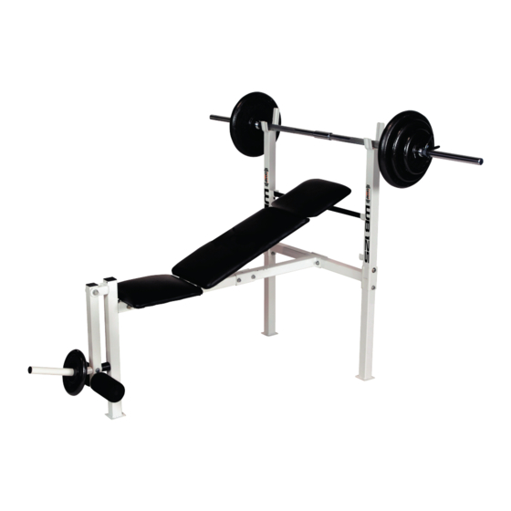
Summary of Contents for Body Champ WB 125
- Page 1 Maximum Weight Limit is 250 lbs. (This includes the userʼs body weight)
- Page 2 SAFETY AND CAUTION SAFETY AND CAUTION W A R N I N G W A R N I N G Before Using Read All The Warnings And Obtain Instruction On The Use Of This Machine! Use Only For Intended Exercise! DO NOT Modify The Machine! Before Beginning Any Exercise Program, Consult With Your Doctor Or Health Physician.
-
Page 3: Warranty Information
WARRANTY INFORMATION CA 91789... - Page 4 BEFORE ASSEMBLY BEFORE ASSEMBLY Take a few minutes to familiarize yourself with the parts and hardware included with your product. Take a few moments to familiarize yourself with the specific parts hardware IMPORTANT PLEASE NOTE: SOME OF THE PARTS AND HARDWARE LISTED ON THE PARTS included with your product.
-
Page 5: Hardware List
HARDWARE LIST IMPORTANT PLEASE NOTE: The hardware listed below is a list of ALL the hardware used on your weight bench. Some of this hardware is already pre installed on your product. Do not be alarmed if you are missing any of these parts. Qty: 8pcs Qty: 3pcs Qty: 1pc... -
Page 6: Parts List
PARTS LIST ITEM# DESCRIPTION Upright(Right) Upright(Left) Down Upright Rear Cross Tube Rear Main Frame Front Main Frame Front Upright Leg Developer Tube Roller Tube Backrest Tube (Long) Backrest Tube (Short) Backrest Adjustment Tube Reinforcement Plate 5/16" X 2 -3/16" Hex Head Bolt 3/8"... - Page 7 PARTS LIST ����� ����������� ��� �� �� 6 . 5 × 1 3 × 1 . 0t W a s h e r � � �� � 5 / 1 6 " × 8 . 0 t N y l o n N u t ��...
-
Page 8: Exploded Diagram
EXPLODED DIAGRAM The following diagram is provided to help you familiarize yourself with the parts and hardware that will be used during the assembly process. Please note that not all of the parts and hardware you see here will be used while you are assembling the machine because some of these items are already pre-installed. - Page 9 UPRIGHT ASSEMBLY STEP 1 A. Insert the RIGHT UPRIGHT ASSEMBLY (1) into the DOWN UPRIGHT ASSEMBLY (3) as shown in diagram. Repeat the same procedure to insert the LEFT UPRIGHT ASSEMBLY (2) into the other DOWN UPRIGHT ASSEMBLY (3). B. Hold the REAR CROSS TUBE (4) in place and secure the REINFORCEMENT PLATE (14) on the right using two HEX BOLTS (15), four WASHERS (22) and two NYLON NUTS (25) as shown.
- Page 10 MAIN FRAME ASSEMBLY STEP 2 A. Insert REAR MAIN FRAME (5) into FRONT MAIN FRAME (6). B. Secure with one REINFORCEMENT PLATE (14) on each side using two HEX BOLTS (15), four WASHERS (22) and two NYLON NUTS (25) as shown in the diagram.
- Page 11 LEG DEVELOPER ASSEMBLY STEP 3 A. Install LEG DEVELOPER (8) to the FRONT UPRIGHT (7), which is attached to the MAIN FRAME ASSEMBLY using one HEX BOLT (18), two WASHERS (23) and one NYLON NUT (26). Do not over-tighten the HEX BOLT (18) as this will prevent the LEG DEVELOPER from functioning smoothly.
- Page 12 BACKREST FRAME ASSEMBLY STEP 4 A. The BACKREST ADJUSTMENT TUBE (13) is an adjustable tube for incline or flat operation. Install on the top notches ensuring that the tabs go into the small holes located on the adjustment brackets as shown. B.
- Page 13 SEAT PAD ASSEMBLY STEP 5 A. Assemble one PAD (35) first at the BOTTOM using two HEX BOLTS (21) and two WASHERS (24). DO NOT over tighten hardware as this may damage your pad. B. The LARGE PAD (36) must be the CENTER pad for proper assembly. Secure the LARGE PAD (36) with four HEX BOLTS (20) and four WASHERS (24).
-
Page 14: Final Check
FINAL CHECK • Make sure all bolts are tightened. • Check for loose parts and components • Check to see if there are any tears or bends in the welding or metal. • Be sure that all adjustment locking devices and safety devices are properly located and fully engaged prior to use! Page 14... - Page 15 Thanks for choosing WB 125 Retailer: ���� ���� ������ ���� ����� ������� ������� ������� �� ����� ������ ����� �������� ���� ����� �������� ������ ����������������������� Page 15 version: 6-16-2009...
Need help?
Do you have a question about the WB 125 and is the answer not in the manual?
Questions and answers