
Related Manuals for Body Champ BRM3671


Summary of Contents for Body Champ BRM3671
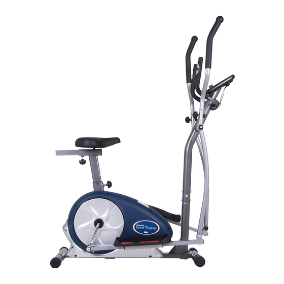
- Page 1 BRM3671 BRM3690 BRM3171 Cardio Dual Trainer This product is intended for indoor, home use only and is not to be used in a commercial setting. OWNER’S MANUAL...
- Page 2 ARE NOT FOLLOWED. The diagram below highlights and reviews many of the important Safety and Warning labels also found on the unit. Please ensure any user of the unit familiarizes themselves with these Safety and Warning guidelines before use. BRM3671/3690/3171 Page 1...
-
Page 3: General Information
21717 Ferrero Parkway, Walnut, CA 91789 - 1 x Philips (”Crosshead”) Screw Driver Telephone: 1 (888) 266A - 6789 Fax: 1 (909) 598 - 6707 Weight Limit Email: info@hupa.net Your product is suitable for users weighing : 250 pounds or less BRM3671/3690/3171 Page 2... -
Page 4: Before Assembly
Ruler (with both Metric and English measurements) Use to measure the length or size of hardware including QTY: 1 bolts to ensure you are using the correct part. Adjustable or flat wrenches Use to securely install parts including nuts and bolts. QTY: 2 BRM3671/3690/3171 Page 3... -
Page 5: Part Listing
Knob Bolt Monitor Wire (Lower) Bolt (M10x58mm) Tool (5mm) Carriage Bolt ( 8x65mm) Tool Hex Bolt (M8x45mm) M8 Bolt Cover Hex Bolt (M8x40mm) M10 Bolt Cover Bolt (M8x20 mm) 1/2" Bolt Cover Bolt (M8x15mm) Handle Bar Cover BRM3671/3690/3171 Page 4... -
Page 6: Exploded View
: : Not all of the parts and hardware you see here will be used while you are assembling the machine because some of these items are already pre-installed. Please use this page only as a reference guide for parts and hardware. BRM3671/3690/3171 Page 5... -
Page 7: Hardware And Tool List
(#26) Round Cap (#67) 1/2" Bolt Cover (#66) M10 Bolt Cover [2 Pieces] (19mm) [2 Pieces] [2 Pieces] [2 Pieces] [2 Pieces] (#65) M8 Bolt Cover (#64) Tool (#63) Tool (5mm) [2 Pieces] [1 Piece] [2 Pieces] BRM3671/3690/3171 Page 6... -
Page 8: Assembly Step
Make sure these two wires are accessible and exposed (as shown) before pro- ceeding to the next step. If they have fallen inside the tube, use a bent wire to “fish” them out. Front Roller BRM3671/3690/3171 Page 7... - Page 9 (Lower) (#62). Slide the Center Post (#02) onto the Main Frame [6 Pieces] (#01) and secure it using six Bolts (#34), six Spring Washers (#45), and six Arc Washers (#43) that were previously removed. (#43) Arc Washer (M8) (#45) Spring Washer (M8) [6 Pieces] [6 pieces] BRM3671/3690/3171 Page 8...
- Page 10 (#05/#06). (#33) Bolt (M8x20 mm) Secure each side with a D Shape Washer (#25), a Round Cap [2 Pieces] (#26), a Washer (#44), and a Bolt (#33). (#26) Round Cap (#44) Washer (M8) [2 Pieces] [2 pieces] BRM3671/3690/3171 Page 9...
- Page 11 Repeat this process on the other side with the Left Pedal Tube (#03) and Left Coupler Bar (#05). (#39) Nylon Nut (M10) [2 Pieces] (#42) Washer (M10) [2 Pieces] (#32) Hex Bolt (M8x40mm) [6 Pieces] (#44) Washer (M8) (#41) Nylon Nut (M8) [6 pieces] [6 Pieces] BRM3671/3690/3171 Page 10...
- Page 12 Repeat this process on the other side with the Right Handle [2 Pieces] Bar (#08) and Right Coupler Bar(#06). Align and attach the Pulse Handle Bar (#09) to the bracket on the Center Post (#02) by securing with two Bolts (#35). (#27) Knob Bolt [2 Pieces] BRM3671/3690/3171 Page 11...
- Page 13 Connect the Wire (Upper) (#61) to the Monitor (#17) and connect the Pulse Sensor Wire (#60) to the Monitor (#17). Secure the (#37) Screw (M5x12mm) Monitor (#17) to the bracket of the Center Post (#02) using four [6 Pieces] Screws (#37) that were previously removed. BRM3671/3690/3171 Page 12...
- Page 14 **Do not remove the Seat (#36) for any reason after you have installed it. Exercising on this unit without the Seat(#36) can result in SERIOUS INJURY. Ensure the seat is locked in place by ightening the two knobs prior to use. BRM3671/3690/3171 Page 13...
- Page 15 However, for your own safety, please make sure to read this entire Owner’s Manual which includes safety instructions and warnings, as well as any safety/warning labels affixed to the product before use. For your safety , please visually and functionally inspect and test the unit after assembly is complete. BRM3671/3690/3171 Page 14...
-
Page 16: Computer Operation
Please remember that the programs in this computer are only meant to be tools to monitor your workout progress; they are not meant to provide medical information or be used for medical purposes. Please consult a physician before beginning any workout program. BRM3671/3690/3171 Page 15... - Page 17 AUTO TURN ON Computer will turn on automatically if movement on the unit is detected, or any button is pressed. RESISTANCE The computer display uses a bar-matrix grid which shows columns up to 16 rectangular increments. LEVEL ADAPTOR INPUT: 100-240V~50/60Hz 0.4A OUTPUT: 9V 1.0A BRM3671/3690/3171 Page 16...
- Page 18 3. If desired, you can preset values for functions of TIME/DIST/CAL/AGE, or, skip through any pre-setting functions by pressing ENTER. • To set values, use UP/DOWN to increase/decrease values. • Press ENTER to confirm desired values. 4. Press START/STOP to begin workout session. BRM3671/3690/3171 Page 17...
-
Page 19: Safety And Maintenance
1 (888) 266A-6789 or 1 (909) 598-9876, or mail in a written request to: Hupa International 21717 Ferrero Parkway Walnut, CA 91789 More detailed information about how to reach our CUSTOMER SUPPORT may be found on Page 2 of the Owner’s Manual under the “CUSTOMER SUPPORT” section. BRM3671/3690/3171 Page 18... -
Page 20: Troubleshooting
- Increase the separation between the equipment and receiver. - Connect the equipment into an outlet on a circuit different from that to which the receiver is connected. - Consult the dealer or an experienced radio/TV technician for help. BRM3671/3690/3171 Page 19... - Page 21 Keep your left leg straight. 2. Return to the starting position slowly. 2. Gently pull your right leg toward your trunk without raising your upper body. Switch leg positions and repeat. BRM3671/3690/3171 Page 20...
- Page 22 Repeat on the other leg. muscles in your left calf stretch. other. Switch leg positions and repeat. Reverse arm positions and BRM3671/3690/3171 Page 21...
- Page 23 This page is left blank intentionally...
- Page 24 THANK YOU FOR YOUR PURCHASE MODEL NO.: BRM3671/BRM3690/BRM3171 Please fill in the information below and keep this manual along with your sales receipt as proof of purchase. Serial Number : Date of Purchase : Retailer : Hupa International 21717 Ferrero Parkway...
Need help?
Do you have a question about the BRM3671 and is the answer not in the manual?
Questions and answers
How do I set level of workout to below.
To set the workout level on the Body Champ BRM3671:
1. Use the UP/DOWN buttons to select the desired program.
2. Press ENTER to confirm.
3. If desired, preset values for TIME, DISTANCE, CALORIES, or AGE by using the UP/DOWN buttons to adjust values, then press ENTER to confirm.
4. Press START/STOP to begin the workout.
5. The resistance level is displayed on the bar-matrix grid with 16 levels available, which can be adjusted manually during the workout.
The machine automatically turns on when movement is detected or any button is pressed and shuts off after 4 minutes of inactivity.
This answer is automatically generated
Como quitar tension a la bicicleta está muy dura la quiero resetear ayuuuda