
Related Manuals for Body Champ VKR 1700


Summary of Contents for Body Champ VKR 1700
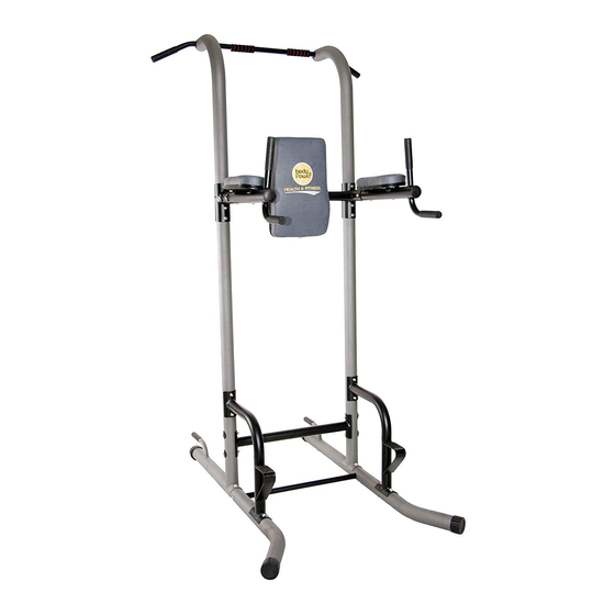
- Page 1 VKR 1700 B o d y C h a m p P o w e r T o w e r * This item is for consumer use only and it is not meant for commercial use. OWN ER’S MAN UA L...
-
Page 2: General Information
General Information Safety Warranty Before you undertake any exercise program, Body Flex Sports warrants your product for please be sure to consult with your doctor. a period of 1 year for the frame and 90 days Frequent strenuous exercise should be on all parts if the item is used for the intended approved by your doctor and proper use purpose, properly maintained and not used... -
Page 3: Hardware List
Hardware List The following hardware and tools are used to assemble your unit. Please take a moment to familiarize yourself with these items. BOLT #15 Carriage Bolt (M8x70 mm) #19 Hex Bolt (M8x35 mm) [4 pieces] [2 pieces] #16 Hex Bolt (M8x75 mm) #20 Hex Bolt (M8x25 mm) [6 pieces] [14 pieces]... -
Page 4: Parts Listing
Parts Listing The following parts list describes all of the parts illustrated on the exploded diagram on the following page. Please note, most of these parts are already pre-assembled on your unit. Description 01LA/01RA Stabilizer Upright Base Upright Support 05L/05R Dip Arm Top Crossbar Bottom Crossbar... -
Page 5: Exploded Diagram
Exploded Diagram VKR1700 Power Tower Page 4... -
Page 6: Assembly Instructions
Assembly Instructions Hardware Required A s s e m b l y S t e p 1 Bolt A. With the help of an assistant, attach the Push Up Bar (#09) to the Left Stabilizer (#01LA) as shown and secure it using two Washers (#23) and two Hex Bolts (#20). - Page 7 Assembly Instructions Hardware Required A s s e m b l y S t e p 2 Bolt With the help of an assistant, attach the Upright Base (#02) to the Left Stabilizer (#01LA) as shown, secure it with two Hex Bolts (#17) and two Nylon Nuts (#25).
- Page 8 Assembly Instructions A s s e m b l y S t e p 3 Hardware Required Bolt Insert the Support Crossbar (#33) in the hole located on the inside of Right Stabilizer (#01RA), secure it with one Washer (#23) and one Hex Bolt (#20). Attach the Bottom Crossbar (#07) to the Right Upright Base #16 Hex Bolt (M8x75 mm) #20 Hex Bolt (M8x25 mm)
- Page 9 Assembly Instructions A s s e m b l y S t e p 4 Hardware Required Bolt Attach the lower part of the Support (#04) to the two Carriage Bolts (#15) which you inserted into the two Stabilizers (#01A) * * * * * * * * * * * * * * * * * * * * * * * * * * * * * during the first step.
- Page 10 Assembly Instructions A s s e m b l y S t e p 5 Hardware Required Bolt Insert the Upright (#03) into the Upright Base (#02) ENSURE THAT THE UPRIGHT (#03) Please refer to NOTE #1 and NOTE #2 on the illustration! #16 Hex Bolt (M8x75 mm) [6 pieces]...
- Page 11 Assembly Instructions A s s e m b l y S t e p 6 Hardware Required Slide the Top Crossbar (#06A) between the two Dip Arms Bolt (#05R & #05L). Insert two Hex Bolts (#18) through the Support Plate B (#11A). Screw one of the Hex Bolts (#18) through the Dip Arm (#05L) and secure it directly into the Top #18 Hex Bolt (M8x65 mm) [4 pieces]...
- Page 12 Assembly Instructions A s s e m b l y S t e p 7 Hardware Required Bolt Attach the Pull up Bar (#08) to the two Uprights (#03) by inserting two Hex Bolts (#19) through two Washers (#23), Pull Up Bar (#08) and then securing them into the two Uprights (#03).
- Page 13 Assembly Instructions A s s e m b l y S t e p 8 Hardware Required Bolt Attach the Backrest (#13A) to the Top Crossbar (#06A) using a total of four Screws (#22) and four Washers (#24). DO NOT OVER TIGHTEN THE SCREWS AS THIS MAY STRIP THE THREAD OR CRACK THE WOOD IN THE BACKREST (#13A).
- Page 14 Assembly Instructions A s s e m b l y S t e p 9 Hardware Required Bolt A. Insert two Screws (#21) and two Washers (#24) through the bottom of the Right Dip Arm (#05R) and secure the Arm Pad (#14) to the Right Dip Arm (#05R).
-
Page 15: Safety Instructions
Safety Instructions • Make sure all bolts are tightened. • Check for loose parts and components • Check to see if there are any tears or bends in the welding or metal. • Be sure that all adjustment locking devices and safety devices are properly engaged prior to use! VKR1700 Power Tower Page 14... - Page 16 Thanks for choosing VKR 1700 Store Location: Version: 8-25...
Need help?
Do you have a question about the VKR 1700 and is the answer not in the manual?
Questions and answers