Table of Contents
Advertisement
Quick Links
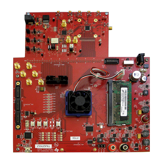
This is the user's guide for the AFE707xEVM evaluation module (EVM). The AFE7070/71 is a dual 14-bit
65-MSPS digital-to-analog converter with an integrated quadrature modulator. The NCO and LVDS output
functions are not available with the AFE7071 but the AFE7070 has both functions. This is the sole
difference between the AFE7070 and the AFE7071. Hereafter, the AFE707x is referred to as AFE7070.
The EVM also includes the CDCM7005 clock synchronizer, which provides the necessary clocks for the
AFE and pattern generator. This EVM is ideally suited for mating with the TSW1400 pattern generation
card for evaluating WCDMA, LTE, or other high-performance modulation schemes.
1
1.1
1.2
1.3
1.4
1.5
2
2.1
2.2
3
3.1
3.2
3.3
3.4
3.5
1
EVM Block Diagram
2
3
4
5
6
7
8
SLOU337A - March 2012 - Revised July 2015
Submit Documentation Feedback
AFE707xEVM Evaluation Module
..........................................................................................................
................................................................................................
..................................................................................................
..............................................................................................
....................................................................................................
.............................................................................................
.............................................................................................................
.............................................................................................
.................................................................................................
.......................................................................................................
.................................................................................................
...........................................................................................
.................................................................................
.................................................................................
List of Figures
.........................................................................................................
....................................................................................................
..............................................................................................
...........................................................................................
..................................................................................................
...............................................................................................
...............................................................................................
Copyright © 2012-2015, Texas Instruments Incorporated
SLOU337A - March 2012 - Revised July 2015
Contents
..........................................................................
User's Guide
.............
AFE707xEVM Evaluation Module
2
2
2
2
3
4
5
5
5
8
8
8
9
10
11
2
4
5
7
8
9
10
11
1
Advertisement
Table of Contents

Related Manuals for Texas Instruments AFE707EVM Series


Summary of Contents for Texas Instruments AFE707EVM Series
-
Page 1: Table Of Contents
..... Two-Tone IMD Performance: LO = 2.1 GHz, DAC Rate = 65 MSPS, IF = 4.5 MHz and 5.5 MHz SLOU337A – March 2012 – Revised July 2015 AFE707xEVM Evaluation Module Submit Documentation Feedback Copyright © 2012–2015, Texas Instruments Incorporated... -
Page 2: Hardware Overview
The ac load impedance is 50 Ω. The input signal level can be between 1 V and 2.6 V peak-to-peak. AFE707xEVM Evaluation Module SLOU337A – March 2012 – Revised July 2015 Submit Documentation Feedback Copyright © 2012–2015, Texas Instruments Incorporated... -
Page 3: Clocking Options
R26. Depending on the software settings, the CDCM7005 may automatically switch to the external clock signal (automatic mode), or require the use of jumper JP3 to select it (manual mode). SLOU337A – March 2012 – Revised July 2015 AFE707xEVM Evaluation Module Submit Documentation Feedback Copyright © 2012–2015, Texas Instruments Incorporated... -
Page 4: Power Supply Options
For a detailed illustration of the EVM’s power supplies, see the circuit schematic included in the Design Files on the AFE7070EVM AFE7071EVM tool pages. AFE707xEVM Evaluation Module SLOU337A – March 2012 – Revised July 2015 Submit Documentation Feedback Copyright © 2012–2015, Texas Instruments Incorporated... -
Page 5: Software Control
• FIFO Settings. This section is only active when the device is in Dual Input Clock mode. It controls the SLOU337A – March 2012 – Revised July 2015 AFE707xEVM Evaluation Module Submit Documentation Feedback Copyright © 2012–2015, Texas Instruments Incorporated... - Page 6 TSW1400). The user can specify the output levels (LVPECL or LVCMOS), a divide ratio, and whether or not each signal is active or high-impedance. AFE707xEVM Evaluation Module SLOU337A – March 2012 – Revised July 2015 Submit Documentation Feedback Copyright © 2012–2015, Texas Instruments Incorporated...
-
Page 7: Screen Shot Of Cdcm7005 Tab
– Save AFE Regs. This command saves the AFE7070 register settings to a text file. – Save CDC Regs. This command saves the CDCM7005 register settings to a text file. SLOU337A – March 2012 – Revised July 2015 AFE707xEVM Evaluation Module Submit Documentation Feedback Copyright © 2012–2015, Texas Instruments Incorporated... -
Page 8: Basic Test Procedure
Connect the J7 (CMOS_CLK) on TSW1400 to J5 (CDC OUT) connector on AFE7071 EVM. • Connect 5-V adapter to J12 on TSW1400. • Turn the switch (SW7) to the On position. AFE707xEVM Evaluation Module SLOU337A – March 2012 – Revised July 2015 Submit Documentation Feedback Copyright © 2012–2015, Texas Instruments Incorporated... -
Page 9: Tsw1400 Quick-Start Operation
• Under Tone selection, select Complex. • Click the Create Tones button. • Click Send. Figure 6. TSW1400 Programming GUI SLOU337A – March 2012 – Revised July 2015 AFE707xEVM Evaluation Module Submit Documentation Feedback Copyright © 2012–2015, Texas Instruments Incorporated... -
Page 10: Afe7070 Software Quick-Start Guide
If no output is observed on the spectrum analyzer, reset the AFE7071 by pressing the SW1 switch on the AFE7071 EVM. AFE707xEVM Evaluation Module SLOU337A – March 2012 – Revised July 2015 Submit Documentation Feedback Copyright © 2012–2015, Texas Instruments Incorporated... -
Page 11: Afe7070 Performance Results
Deleted WCDMA ACPR: LO = 2 GHz, DAC Rate = 57.6 MHz, 0-MHz Offset image. NOTE: Page numbers for previous revisions may differ from page numbers in the current version. SLOU337A – March 2012 – Revised July 2015 Revision History Submit Documentation Feedback Copyright © 2012–2015, Texas Instruments Incorporated... - Page 12 STANDARD TERMS AND CONDITIONS FOR EVALUATION MODULES Delivery: TI delivers TI evaluation boards, kits, or modules, including any accompanying demonstration software, components, or documentation (collectively, an “EVM” or “EVMs”) to the User (“User”) in accordance with the terms and conditions set forth herein. Acceptance of the EVM is expressly subject to the following terms and conditions.
- Page 13 FCC Interference Statement for Class B EVM devices NOTE: This equipment has been tested and found to comply with the limits for a Class B digital device, pursuant to part 15 of the FCC Rules. These limits are designed to provide reasonable protection against harmful interference in a residential installation.
- Page 14 【無線電波を送信する製品の開発キットをお使いになる際の注意事項】 開発キットの中には技術基準適合証明を受けて いないものがあります。 技術適合証明を受けていないもののご使用に際しては、電波法遵守のため、以下のいずれかの 措置を取っていただく必要がありますのでご注意ください。 1. 電波法施行規則第6条第1項第1号に基づく平成18年3月28日総務省告示第173号で定められた電波暗室等の試験設備でご使用 いただく。 2. 実験局の免許を取得後ご使用いただく。 3. 技術基準適合証明を取得後ご使用いただく。 なお、本製品は、上記の「ご使用にあたっての注意」を譲渡先、移転先に通知しない限り、譲渡、移転できないものとします。 上記を遵守頂けない場合は、電波法の罰則が適用される可能性があることをご留意ください。 日本テキサス・イ ンスツルメンツ株式会社 東京都新宿区西新宿6丁目24番1号 西新宿三井ビル 3.3.3 Notice for EVMs for Power Line Communication: Please see http://www.tij.co.jp/lsds/ti_ja/general/eStore/notice_02.page 電力線搬送波通信についての開発キットをお使いになる際の注意事項については、次のところをご覧くださ い。http://www.tij.co.jp/lsds/ti_ja/general/eStore/notice_02.page SPACER EVM Use Restrictions and Warnings: 4.1 EVMS ARE NOT FOR USE IN FUNCTIONAL SAFETY AND/OR SAFETY CRITICAL EVALUATIONS, INCLUDING BUT NOT LIMITED TO EVALUATIONS OF LIFE SUPPORT APPLICATIONS.
- Page 15 Notwithstanding the foregoing, any judgment may be enforced in any United States or foreign court, and TI may seek injunctive relief in any United States or foreign court. Mailing Address: Texas Instruments, Post Office Box 655303, Dallas, Texas 75265 Copyright © 2015, Texas Instruments Incorporated...
- Page 16 IMPORTANT NOTICE Texas Instruments Incorporated and its subsidiaries (TI) reserve the right to make corrections, enhancements, improvements and other changes to its semiconductor products and services per JESD46, latest issue, and to discontinue any product or service per JESD48, latest issue.
- Page 17 Mouser Electronics Authorized Distributor Click to View Pricing, Inventory, Delivery & Lifecycle Information: Texas Instruments AFE7070EVM AFE7071EVM...
Need help?
Do you have a question about the AFE707EVM Series and is the answer not in the manual?
Questions and answers