Aventics HF03 Operating Instructions Manual
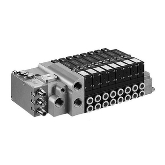
Double multiple plug connector
Hide thumbs
Also See for HF03:
- Operating instructions manual (120 pages) ,
- Operating instructions manual (180 pages)

Related Manuals for Aventics HF03


Summary of Contents for Aventics HF03
- Page 1 Operating Instructions Double Multiple Plug Connector HF03 / HF02 1987765492/08.2014, Replaces: 06.2002, EN...
-
Page 3: Table Of Contents
AVENTICS | HF03 / HF02 | 1987765492–BDL–001–AB Contents Contents Notes on safety ..............5 System architecture ............6 Construction and design............... 7 Function..................... 7 I/O connections ................7 Installation ................. 8 HF 03 mounting................8 HF 02 mounting................9 Marking and identification ............10 Electrical connection ..............10... -
Page 5: Notes On Safety
AVENTICS | HF03 / HF02 | 1987765492–BDL–001–AB Notes on safety Notes on safety Please observe the notes on safety. This valve system may only be used for industrial applications. Installation may only be performed in a voltage-free and pressure- free state and only by a qualified technician. -
Page 6: System Architecture
System architecture System architecture The versatility and flexibility of this valve system enables AVENTICS to support your automation tasks. The valves are completely assembled and tested according to your requirements; the electrical connection is made via multiple plug connectors. I/O modules are in- stalled in the system as per your specifications. -
Page 7: Construction And Design
AVENTICS | HF03 / HF02 | 1987765492–BDL–001–AB System architecture Construction and design valve system with The HF 03 / HF 02 valve system is composed of the following double multiple plug components depending on the order: connector and passive right end plate for connecting the pneumatics,... -
Page 8: Installation
AVENTICS | HF03 / HF02 | 1987765492–BDL–001–AB Installation Installation HF 03 mounting Dimensions The valve system can be mounted in any desired position with 4 screws (e.g. M6) or placed on a DIN rail, DIN EN 50022, 35 × 15. -
Page 9: Hf 02 Mounting
AVENTICS | HF03 / HF02 | 1987765492–BDL–001–AB Installation HF 02 mounting Dimensions The valve system can be mounted in any desired position with 4 screws (e.g. M6) or placed on a DIN rail, DIN EN 50022, 35 × 15. PE connection... -
Page 10: Marking And Identification
AVENTICS | HF03 / HF02 | 1987765492–BDL–001–AB Installation Marking and identification I/O module, passive The I/O connections are inscribed directly on the I/O modules. Fig. 4: I/O module, passive Electrical connection M12×1 connections for The passive I/O module makes it possible to connect a sensor or passive I/O modules an actuator to each of the eight M12×1 connections. -
Page 11: 3.4.1 M12×1 Connections
AVENTICS | HF03 / HF02 | 1987765492–BDL–001–AB Installation LED display for the The supply voltage's presence is shown by a green LED. supply voltage 3.4.1 M12×1 connections M12×1 connections for A sensor or an actuator can be connected to each of the eight the I/O modules M12×1 connections of an I/O module via M12×1 plug (4 or 5-pin). -
Page 12: 3.4.2 Multiple Plug Connection For I/O Modules
AVENTICS | HF03 / HF02 | 1987765492–BDL–001–AB Installation 3.4.2 Multiple plug connection for I/O modules Both the multiple plug connector I for the valve controls (right next to the valves) and the multiple plug connector II for the I/O modules (right next to the I/O modules) are located on the adapter plate. -
Page 13: Making Connections
AVENTICS | HF03 / HF02 | 1987765492–BDL–001–AB Installation Mating plug II 1. Select a suitable sealing element and insert it into the mating assembly plug's terminal fitting: red: cable Ø 9.0 ... 13.0 mm white: cable Ø 11.5 ... 15.5 mm 2. -
Page 14: Testing And Start-Up
AVENTICS | HF03 / HF02 | 1987765492–BDL–001–AB Testing and start-up Testing and start-up Testing The functional reliability and operating method of the actuator/sensor controls should be checked before start-up. Start-up Before switching the system on, ensure that it is in a defined state! Also ensure that all manual overrides are set to zero. -
Page 15: Characteristics, Service Parts And Accessories
AVENTICS | HF03 / HF02 | 1987765492–BDL–001–AB Characteristics, service parts and accessories 2. Put the additional I/O module in place. Ensure that the gasket has been inserted properly and that the contacts have been plugged in. 3. Screw the I/O module tight (3 hexagon socket-head screws, DIN 912 M4, wrench width 3). -
Page 16: Service Parts And Accessories
AVENTICS | HF03 / HF02 | 1987765492–BDL–001–AB Characteristics, service parts and accessories Table 3: Electrical Rated voltage 24 V DC (-15& / +20%) Max. current load: Signal line 0,5 A Supply line 0,5 A Total supply line current 4.0 A/module Fuse for I/O modules 8.0 A medium time lag... - Page 18 German language. 1987765492–BDL–001–AB/08.2014 Subject to modifications. © All rights reserved by AVENTICS GmbH, even and especially in cases of proprietary rights applications. It may not be reproduced or given to third parties without its consent.
Need help?
Do you have a question about the HF03 and is the answer not in the manual?
Questions and answers