Table of Contents
Advertisement
Quick Links
DESCRIPTION OF MODELS
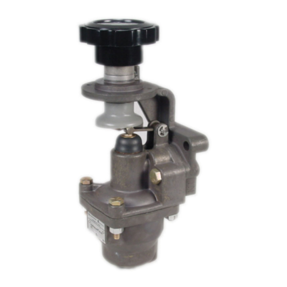
The H-4 Type CONTROLAIR Valves are knob
operated 3-way pressure graduating valves. The knob
actuates the pressure graduating portion to increase,
decrease or maintain graduated air pressure to a
separate delivery line.
In knob "release" position the delivery line is connected
to exhaust. Knob rotation from release position
actuates the graduating portion to deliver graduated
pressure to a delivery line according to the value of
control spring being used. The knob is self holding in
all positions.
The H-4 CONTROLAIR Valve is available with either
clockwise rotation or counterclockwise rotation of the
knob increasing pressure.
WARNING: INSTALLATION AND
MOUNTING
The user of these devices must conform to all applicable
electrical, mechanical, piping and other codes in the
installation, operation or repair of these devices.
INSTALLATION! Do not attempt to install, operate or
repair these devices without proper training in the
technique of working on pneumatic or hydraulic systems
and devices, unless under trained supervision.
Compressed air and hydraulic systems contain high
levels of stored energy. Do not attempt to connect,
disconnect or repair these products when a system is
under pressure. Always exhaust or drain the pressure
from a system before performing any service work.
Failure to do so can result in serious personal injury.
MOUNTING!
Devices
positioned in such a manner that they cannot be
accidentally operated.
SM-800.6516
H-4 CONTROLAIR
Service Information
should
be
mounted
®
VALVE
Table of Contents
Description of Models .................................. 1
Technical Data .............................................. 2
Installation ..................................................... 2
Maintenance and Repair ............................... 2
Outline Dimensions ....................................... 3
Description of Operation................................ 4
Symbol .......................................................... 4
Diagrammatic View ....................................... 4
Identity Schedule ........................................... 5
Exploded Views ............................................. 6
Parts List ....................................................... 7
Repair Kit List ................................................ 8
Maintenance and Repair ............................... 9
Function ................................................. 10
Pressure Range ..................................... 10
Leakage ................................................. 10
Flow Capacity ........................................ 10
Response ............................................... 10
and
Test Set-up ............................................ 10
Test Diagram ................................................. 11
Warnings and Warranties .............................. 12
Page
Advertisement
Table of Contents

Subscribe to Our Youtube Channel
Related Manuals for Aventics CONTROLAIR H-4


Summary of Contents for Aventics CONTROLAIR H-4
-
Page 1: Table Of Contents
® H-4 CONTROLAIR VALVE Service Information DESCRIPTION OF MODELS The H-4 Type CONTROLAIR Valves are knob operated 3-way pressure graduating valves. The knob actuates the pressure graduating portion to increase, decrease or maintain graduated air pressure to a separate delivery line. In knob “release”... -
Page 2: Technical Data
Installation and General Maintenance Recommendations Installation General Maintenance Before installing the Controlair® Valve, all air lines in Maintenance periods should scheduled the system should be blown clean to remove any accordance with frequency of use and working moisture, dirt, or harmful contamination. Strainers are environment of the Controlair Valve. -
Page 3: Outline Dimensions
OUTLINE DIMENSIONS Clockwise rotation of the knob increases pressure unless otherwise specified. 240 ° max. effective knob rotation. (Adjustable) Page 3... -
Page 4: Description Of Operation
DESCRIPTION OF OPERATION VALVE FUNCTION Outlet Exhaust Inlet Description of Operation When the knob is in released position, the “IN” port is closed to supply pressure and “OUT” port is open to exhaust. Note in the diagrammatic, when the knob is rotated to increase pressure, the shaft and cam are also rotated. -
Page 5: Identity Schedule
IDENTITY SCHEDULE New H-4 Old H-4 Delivery New Valve Old Valve New Control Old Control Remarks Complete Complete Pressure Portion Portion Spring Spring Part Part Part Part Part Part Number & Number Number Number Number Number Color Code R431002818 P -050967 0-65 psi R431002874 P -051133 R431003732 P -055442-00000... -
Page 6: Exploded Views
EXPLODED VIEW Note: 1. See page 5 & 7 for part number 2. See page 8 for repair kits 3. Matched/lapped set of item 13 & 8 are in kit, P/N R431003895 ), page 8 R431003895 13 (Note 3) 8 (Note 3) Valve Control Portion Complete (See Identity Schedule, Page 5) See Identity Schedule... -
Page 7: Parts List
PARTS LIST Ref. Qty Description New Part Number Old Part Number Adjusting screw R431006770 P -066209-00000 Spring housing with nut R431006822 P -066488-00002 Nuts, 5/16” – 18 R431002419 P -049901-00020 Spring set R431000036 -526347-00000 Control Spring (See identity schedule, Pg. 4) (See identity schedule, Pg. -
Page 8: Repair Kit List
REPAIR KITS Quantity New Part Old Part Num- Description Number Valve Minor Graduating Valve Portion – repair kit (includes R431003895 P -055687-K0000* items 8,9,10,11,12,13, 14) see note Major Graduating Valve Portion – repair kit (includes R431004887 P -059028-K0000 items 15,16,17,18 and kit R431003895) R431006425 P -064421-K0000 Knob Kit (includes items 33a, 33b,33c) -
Page 9: Maintenance And Repair
Repair and Maintenance Instructions 4 Controlair Valves. This is the adjusting screw item Repair and Maintenance Instructions #1, that varies the output pressure. When it has been determined that the Controlair® Valve requires repairs, the following general Graduated Output Pressure Adjustments instructions are recommended. -
Page 10: Testing
Testing and Test Set-Up (See Test Arrangement Diagram) Testing travel position, the delivery volumes should start to After any repair or adjustments, the H-4 Controlair® fill within the time limits shown in Table 1. Valve should be tested using the following procedures Move the handle quickly from full travel position to and test arrangements described in this section. -
Page 11: Test Diagram
REQUIRED FOR LOW SPRING RANGE VALVES ON LY. CLEAN, DRY, CHEMICAL FREE AIR SUPPLY 200 PSI (14 Bar) MAXIMUM (OR 20 PSI (1 Bar) ABOVE MAXIMUM DELIVERY PRESSURE OF ANY VALVE TESTED). AVENTICS P/N (PD-020031-00191) RECOMMENDED AVENTICS P/N R432016357 (PR-007816-00019) Page 11... -
Page 12: Warnings And Warranties
No charge will be made for labor with respect to defects covered by this Warranty, provided that the work is done by AVENTICS or any of its authorized service facilities. - Page 13 SM-800.6516/August 2017 Subject to change. Printed in United States. AVENTICS Corporation. This document, as well as the data, specifications, and other information set forth in it, are the exclusive property of AVENTICS. It may not be reproduced or given to third parties without its consent.
Need help?
Do you have a question about the CONTROLAIR H-4 and is the answer not in the manual?
Questions and answers