Table of Contents
Advertisement
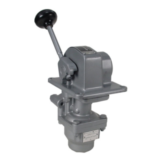
Description of Models
The H-2 Type Controlair Valves are handle operated 3-
way pressure graduating control valves. The handle actu-
ates the pressure-graduating portion to increase, de-
crease or maintain a graduated air pressure to the deliv-
ery line.
When the handle is in the "OFF" or release position the
delivery line is connected to exhaust, except in the pre-
loaded type Controlairs. Handle movement from the
"OFF" or release position actuates the pressure graduat-
ing portion to deliver a graduated pressure according to
the value of the control spring.
Models
There are several models with similar valve functions, but
different handle operating characteristics.
H-2-X Controlair Valve -Handle is spring returned to the
off position from all positions in the handle travel. Some
special models exist. See notes on Identity schedule on
page 9.
H-2-LX Controlair Valve - Handle is spring returned to off
position from all positions except at the maximum pres-
sure setting. The handle is held in the extreme position by
a mechanical detent.
H-2-FX
Controlair Valve - Handle is equipped with a
friction brake that will hold the handle in any position se-
lected in the handle travel.
H-2-EX Controlair Valve - Handle is spring returned to
"OFF" position from all other positions in the handle travel.
The "OUTLET" pressure increases from 0 to 40% of the
control pressure in the first 60 degrees of handle travel.
The outlet pressure then increases to maximum control
pressure in the remaining 32 degrees of handle travel.
H-2-EFX Controlair Valve - Handle travel and valve func-
tions are the same as H-2-EX except it is equipped with a
friction brake that holds the handle in any position select-
ed in the handle travel.
H-2-ES Controlair Valve - Valve is similar to H-2-EX ex-
cept no handle return spring or friction brake in the handle
travel.
H-2-EFS Controlair Valve- Valve is similar to H-2-EFX
except is preloaded in "release" position and handle return
spring is only effective in the first 28° of 86 degrees of
handle travel.
SM-800.6502
H-2 CONTROLAIR
Service Information
®
VALVE
Table of Contents
Page
1
2
2
2
3 & 4
5
6
7
7
8 & 9
10
11 & 12
13
14
15 & 16
17
17
17
17
17
17
17
17
18
Advertisement
Table of Contents

Related Manuals for Aventics Controlair H-2 Series


Summary of Contents for Aventics Controlair H-2 Series
-
Page 1: Table Of Contents
® H-2 CONTROLAIR VALVE Service Information Description of Models The H-2 Type Controlair Valves are handle operated 3- way pressure graduating control valves. The handle actu- ates the pressure-graduating portion to increase, de- Table of Contents Page crease or maintain a graduated air pressure to the deliv- ery line. -
Page 2: Warnings
Installation and General Maintenance Recommendations WARNING: INSTALLATION GENERAL MAINTENANCE AND REPAIR AND MOUNTING RECOMMENDATIONS The user of these devices must conform to all appli- cable electrical, mechanical, piping and other codes Maintenance periods should be scheduled in accordance in the installation, operation or repair of these devic- with frequency of use and working environment of the Con- trolair Valve. -
Page 3: Outline Dimensions 3
Outline View H-2 Controlair® Valve Page 3... - Page 4 Outline View H2-E Controlair® Valve 4.69 .34 DIA 2.38 .38 R 1.00R HOLE IN PANEL 1.50R FOR MOUNTING 2.25 4.44 4.00 1.94 1.50R 2.00 1.00R 2.50 4.69 5.88R 46° 1.63 92° YOKE ASSEMBLY AS SHOWN REVERSE 1.50 FOR 78° .25 MAX. THICKNESS 2.66 OF PANEL...
-
Page 5: Description Of Operation
Description of Operation For H-2 Controlair® sures changes. These air pressure changes When the handle is in released position, the can be caused by line leakage, temperature “IN” port is closed to supply pressure and the change or load feedback. If air pressure at “OUT”... -
Page 6: Maintenance And Repair
Repair and Maintenance Instructions sure setting. Turning the adjusting screw in raises the Repair and Maintenance Instructions maximum pressure. Turning the screw out decreases When it has been determined that the Controlair® the maximum pressure. The maximum control pres- Valve requires repairs, the following general instruc- sure adjustment should not exceed the maximum tions are recommended. -
Page 7: Graphical Symbol
DIAGRAMMATIC VIEW VALVE SYMBOL H-2 CONTROLAIR® VALVE RELEASE POSITION FULL TRAVEL LEGEND—PIPE BRACKET IN - SUPPLY OUT - GRADUATED DELIVERY CAM FOLLOWER INLET & EXHAUST SENSING PORT ORIFICE VALVE UNIT SUPPLY VALVE DIAPHRAGM EXHAUST VALVE ADJUSTING SCREW EXHAUST PORT Page 7... - Page 8 H-2 IDENTITY SCHEDULE Control New Cam Old Cam New Valve Old Valve +Model Complete Complete Pressure New Control Spring Control Spring Portion Portion Portion Portion Handle Remarks Part Number Part Number Range (PSI.) & Color Code & Color Code Complete Complete Complete Complete...
-
Page 9: Identity Schedule 8
Identity Schedule Note 1 Same as R431002640 (P -050493-00003) except Items 23 & 42 are chrome plated. Note 2 Same as 431002640 (P50493-00003) except cam housing and escutcheon plate, Item 23 and 25, part numbers R431007253 (P -067695-00000) or R431002638 (P -048316-00000). Note 3 Same as R431002638 (P -050493-00001) except less yoke, handle, nut, knob and paint, Items 42,43,44 &... -
Page 10: Exploded View
EXPLODED VIEW H-2-X CONTROLAIR® H-2-LX CONTROLAIR® NOTE: SEE PAGE 11 & 12 FOR PART NUMBERS SEE PAGE 13 FOR REPAIR KITS MATCHED/LAPPED SET OF ITEM 8 & 13 ARE IN KIT, P/N R431003895 (R431003895) PAGE 11. H-2-EFX CONTROLAIR H-2-EFS CONTROLAIR (has spring (38), arbor (37) and brake). H-2-FX CONTROLAIR BRAKE ASSY. -
Page 11: Part List 11
H-2 Controlair® Valve Parts List REF. QTY. DESCRIPTION New P/N H-2-X Old P/N H-2-X New P/N H-2-FX Old P/N H-2-FX New P/N H-2-LX Old P/N H-2-LX Complete Device P –050493-0000X P –050494-0000X P –050499-0000X Adjusting screw R431006770 P –066209-00000 R431006770 P –066209-00000 R431006770 P –066209-00000... - Page 12 H-2 Controlair® Valve Parts List REF. DESCRIPTION New P/N H-2-EX Old P/N H-2-EX New P/N H-2-EFX Old P/NH-2-EFX New P/N H-2-ES Old P/N H-2-ES New P/N H-2-EFS H-2-EFS Complete Device P –050925-0000X P –051846-0000X P –062293-00003 P –063247-0000X Adjusting Screw R431006770 P –066209-00000 R431006770...
-
Page 13: Repair Kit List
Repair Kits for H-2 Controlair® Valves Quantity New Part Number Old Part Number Description Per Valve R431003895 * P –055687-K0000 Minor Graduating Valve Portion-Repair Kit Note 1 Includes items 8, 9, 10, 11, 12, 13 and 14 R431004887 * P –059028-K0000 Major Graduating Valve Portion-Repair Kit Note 1 Includes items 15, 17, 18 and Kit R431003895... -
Page 14: Full Pressure Feature
Full Pressure Feature for H-2 Controlair® The full pressure feature was added to H-2 Controlair Valves to provide pressure graduation for the initial engagement of a clutch and then to lock the clutch at full line pressure. It is particular- ly attractive on valves that are mounted in a vertical position. -
Page 15: Assembly Sectional Views 15
ASSEMBLY VIEW Page 15... - Page 16 ASSEMBLIES The following H-2-X, H-2-LX, and H-2-FX CONTROLAIR Valves are assembled as shown where handle location or push/pull handle action is required on special panel configuration. Model New P/N Old P/N Configuration Model New P/N Old P/N Configuration H-2-X R431007252 P -067694-00003 Figure No. 1 Rev. H-2-X R431007324 P -068544- No.
-
Page 17: Testing
Testing and Test Set-Up (See Test Arrangement Diagram) Testing Moving the handle from “OFF” position to the full After any repair or adjustments, the H-2 Controlair travel position, the delivery volumes should start to Valve should be tested using the following procedures fill within the time limits shown in Table 1. -
Page 18: Test Diagram
Test Arrangement Diagram Notes: 1. AVENTICS Taskmaster Timing Volumes, part number R431002899 (TM–058887-00225) can be used for the volumes indicated. 2. The supply air line to the valve and the delivery lines must be full size as shown. Line must not exceed 3 Ft. - Page 19 No charge will be made for labor with respect to defects covered by this Warranty, provided that the work is done by AVENTICS or any of its authorized service facilities.
- Page 20 SM-800.6502/May 2014 Subject to change. Printed in United States. AVENTICS Corporation. This document, as well as the data, specifications, and other information set forth in it, are the exclusive property of AVENTICS. It may not be reproduced or given to third parties without its consent.
Need help?
Do you have a question about the Controlair H-2 Series and is the answer not in the manual?
Questions and answers