Table of Contents
Advertisement
Quick Links
DESCRIPTION OF MODELS
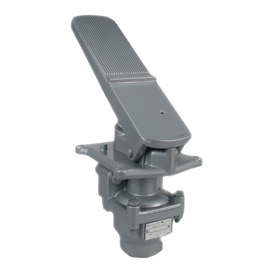
The H-1 and H-1-A Type CONTROLAIR Valves are spring
returned pedal actuated 3-way pressure graduating valves. A
pedal actuates the valve to increase, decrease or maintain
graduated air pressure to a separate delivery line.
In pedal release position, the delivery line is connected to
exhaust. Depressing the pedal actuates the graduating portion to
deliver graduated pressure to a delivery line according to the
value of control spring being used.
MODELS
H-1 CONTROLAIR Valve: The H-1 CONTROLAIR Valve is a
pedal actuated, 3-way pressure regulating valve, suitable for
applications where the valve portion extends below the floor level.
Depressing the pedal increases the outlet delivery pressure,
releasing the pedal decreases the delivery pressure. The pedal is
self-returning from all depressed positions.
H-1 CONTROLAIR Valve (light pedal force): This version of the
H-1 operates identically to the standard H-1, but has a
considerably lighter pedal force that makes it especially suited for
throttle controls. This model also offers an alternative piping
arrangement as the valve portion from the H-2 Valve version is
utilized. A formed steel pedal with a rubber tread is utilized on this
model.
H-1-A CONTROLAIR Valve: the H-1-A CONTROLAIR Valve is a
pedal actuated 3-way pressure regulating valve that is designed
for installations in which its operator is standing or in which part of
the valve cannot extend below floor levels. Depressing its pedal
increases the outlet delivery pressure. Releasing the pedal
decreases the outlet delivery pressure. The pedal is self-returning.
WARNING: INSTALLATION AND
MOUNTING
The user of these devices must conform to all applicable
electrical, mechanical, piping and other codes in the
installation, operation or repair of these devices.
INSTALLATION! Do not attempt to install, operate or repair
these devices without proper training in the technique of
working on pneumatic or hydraulic systems and devices,
unless under trained supervision.
Compressed air and hydraulic systems contain high levels of
stored energy. Do not attempt to connect, disconnect or
repair these products when a system is under pressure.
Always exhaust or drain the pressure from a system before
performing any service work. Failure to do so can result in
serious personal injury.
SM-800.6501
H-1 & H-1-A CONTROLAIR
Service Information
®
VALVE
MOUNTING! Devices should be mounted and
positioned in such a manner that they cannot be
accidentally operated.
H-1 CONTROLAIR
VALVE
Table of Contents
Description of Models ................................... 1
Technical Data ............................................... 2
Installation ...................................................... 2
Maintenance and Repair ................................ 2
Outline Dimensions (H-1) ............................... 3
Outline View ................................................... 4-5
Description of Operation ................................ 6
Symbol ........................................................... 6
Diagrammatic View ........................................ 6
Identity Schedule ........................................... 7
Exploded Views ............................................. 8
Parts List ........................................................ 9
Repair Kit List................................................. 10-11
Maintenance and Repair Instructions ............. 12-13
Adjustment and Repair Instructions ............... 12-13
Testing:
Function .................................................. 14
Pressure Range ...................................... 14
Leakage .................................................. 14
Flow Capacity ......................................... 14
Response................................................ 14
Test Set-up ............................................. 14
Test Diagram ................................................. 15
Warnings and Warranties .............................. 16
H-1-A CONTROLAIR
VALVE
Page
Advertisement
Table of Contents

Related Manuals for Aventics CONTROLAIR H-1


Summary of Contents for Aventics CONTROLAIR H-1
-
Page 1: Table Of Contents
® H-1 & H-1-A CONTROLAIR VALVE Service Information DESCRIPTION OF MODELS MOUNTING! Devices should be mounted and positioned in such a manner that they cannot be The H-1 and H-1-A Type CONTROLAIR Valves are spring accidentally operated. returned pedal actuated 3-way pressure graduating valves. A pedal actuates the valve to increase, decrease or maintain graduated air pressure to a separate delivery line. -
Page 2: Technical Data
Installation and General Maintenance Recommendations Installation General Maintenance ® Before installing the Controlair Valve, all air lines in the Maintenance periods should be scheduled in accordance system should be blown clean to remove any moisture, dirt, with frequency of use and working environment of the or harmful contamination. -
Page 3: Outline Dimensions (H-1)
® H-1 CONTROLAIR VALVES OUTLINE DIMENSIONS Page 3... -
Page 4: Outline View
® H-1 CONTROLAIR VALVE LIGHT PEDAL FORCE OUTLINE VIEW Page 4... -
Page 5: Outline View
® H-1-A CONTROLAIR VALVES OUTLINE VIEW Page 5... -
Page 6: Description Of Operation
DESCRIPTION OF OPERATION Description of Operation VALVE When the pedal is in released position, the “IN” port is SYMBOL closed to supply pressure and “OUT” port is open to exhaust. Note: In the diagrammatic, when the pedal is depressed downward to increase pressure, the pedal forces the follower to push down the pressure control plunger, closing the lower exhaust valve and opening the upper supply valve, which permits air to flow to out port delivery... -
Page 7: Identity Schedule
IDENTITY SCHEDULE Control Control Control Valve Valve Model Complete Complete Pressure Spring Spring Portion Portion Remarks Part Part Range New Part Old Part Old Part Number Number (PSI) Number Number Number Number R431002613 P -050208-00001 0-65 psi R431003732 P -055442-00000 R431002874 P -051133-00001 R431002614... -
Page 8: Exploded Views
EXPLODED VIEW H-1 (Light Pedal) H-1, H-1-A R431005617 (P -060921-00001 Series) Part No. R431003714 (P -055409-00000) Diaphragm with Exhaust Valve Seat. Complete NOTE: (Includes No. 8, 9, 10 11 & 12) See page 9 & 10 for part numbers. See page 11 for repair kits Match/lapped set of items 8 &... -
Page 9: Parts List
PARTS LIST Control Portions H-1-A+New H-1-A+ Old P/ New H-1++ Lt. Old P/N H-1++ New P/N H-1+ Old P/N H-1+ Item Description Pedal Lt. Pedal Cast Body Cast Body P -051085- P -051085- P -060925- P -060925- P -051133- P -051133- 00000 0000* 00000*... -
Page 10: Repair Kit List
PARTS KITS H-1 Type (P -050208-00000 and P-052570-00000 Series) Service Description New Part No. Old Part No. 3/8” -16x1¾ Cap screws R431000161 -850563-00000 Washer 3/8 lock R431004331 P -049982-00013 Pedal bracket complete R431007392 P -069068-00001 Pedal pin 3/8” x 2 7/8 See Repair Kits See Repair Kits Retaining Rings See Repair Kits See Repair Kits... - Page 11 REPAIR KITS FOR H-1 AND H-1-A Control Portion and Lever Kits (See pages 8 & 9) Part Number Quantity Description Per Valve R431003895 Minor graduating valve portion - - repair kit (includes items (P -055687-K0000*) 8,9,10,11,12,13, 14) see note R431004887 Major graduating valve portion –...
-
Page 12: Maintenance And Repair Instructions
MAJOR REPAIR AND MAINTENANCE, ADJUSTMENTS H-1 Adjustment (reference page 15 for test set- Major Repair and Maintenance Instructions up and page 10 for part references) With the H-1 Controlair Valve pedal fully released, turn the adjusting screw at the bottom of housing When it is determined that the Controlair Valve requires clockwise until the delivery gauge begins to move shop repairs (see page 2 for general maintenance and... - Page 13 MAJOR REPAIR AND MAINTENANCE, ADJUSTMENTS (continued) H-1 (light pedal) Adjustment (ref. Page 15 for test set-up and page 10 for part references) 4. Check delivered air pressure from valve. It With the H-1 Controlair Valve pedal fully released, should be the pressure range indicated on turn the adjusting screw at the bottom of housing identity schedule, page 7, for the part number clockwise until the delivery gauge begins to move...
-
Page 14: Function
TESTING AND TEST SET-UP The H-1, H-1 (light pedal) and H-1-A Controlair 3. Leakage: Set supply pressure to 20 psi above maxi- Valve can be tested after repair using the test mum delivery pressure of valve being tested. Using arrangement shown below. soap solution, coat the valve at pipe bracket and spring housing parting lines. -
Page 15: Test Diagram
#6 SINGLE BRAID HOSE OPTIONAL: REQUIRED FOR LOW SPRING RANGE VALVES ONLY. CLEAN, DRY, CHEMICAL FREE AIR SUPPLY 200 PSIG MAXIMUM (OR 20 PSIG ABOVE MAXIMUM DELIVERY PRESSURE OF ANY VALVE TESTED). AVENTICS P/N PD-020031-00191 RECOMMENDED: AVENTICS P/N/ R432016359 (PR-007816-00010) Page 15... -
Page 16: Warnings And Warranties
No charge will be made for labor with respect to defects covered by this Warranty, provided that the work is done by AVENTICS or any of its authorized service facilities.
Need help?
Do you have a question about the CONTROLAIR H-1 and is the answer not in the manual?
Questions and answers