Advertisement
Quick Links
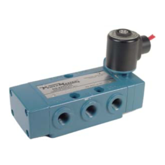
PowerMaster®
All former SuperSpool Valves (except special RailCar versions) are
WARNING:
INSTALLATION AND MOUNTING
The user of these devices must conform to all applicable
electrical, mechanical, piping and other codes in the
installation, operation or repair of these devices.
INSTALLATION! Do not attempt to install, operate or
repair these devices without proper training in the
technique of working on pneumatic or hydraulic systems
and devices, unless under trained supervision.
Compressed air and hydraulic systems contain high levels
SM-300.8000
POWERMASTER
Former SUPER SPOOL
PNEUMATIC DIRECTIONAL VALVE
SERVICE INFORMATION
SuperSpool™
now referred to as PowerMaster Valves.
VALVES
®
AND
VALVES
™
of stored energy. Do not attempt to connect, disconnect or
repair these products when a system is under pressure.
Always exhaust or drain the pressure from a system
before performing any service work. Failure to do so can
result in serious personal injury.
MOUNTING! Devices should be mounted and positioned
in such a manner that they cannot be accidentally
.
operated
SuperSpool™
Advertisement


Need help?
Do you have a question about the PowerMaster Series and is the answer not in the manual?
Questions and answers