Aventics HF02 Operating Instructions Manual
Interbus valve system and bus coupler cms, l-design with fiber optics and diagnosis
Hide thumbs
Also See for HF02:
- Operating instructions manual (18 pages) ,
- Operating instructions manual (180 pages)
Table of Contents
Advertisement
Available languages
Available languages
Quick Links
Advertisement
Chapters
Table of Contents

Related Manuals for Aventics HF02


Summary of Contents for Aventics HF02
- Page 1 Betriebsanleitung | Operating instructions Ventilsystem HF03/HF02 und Buskoppler CMS, L-Design mit Lichtwellenleiter und Diagnose Valve system HF03/HF02 and bus coupler CMS, L-Design with Fiber Optics and Diagnosis INTERBUS R412005655/10.2014, Replaces: 08.2004, DE/EN...
-
Page 3: Table Of Contents
AVENTICS | INTERBUS | R412005655–BDL–001–AB Inhalt Inhalt Zu dieser Dokumentation ..........5 Gültigkeit der Dokumentation..........5 Erforderliche und ergänzende Dokumentationen ...5 Darstellung von Informationen ..........6 1.3.1 Sicherheitshinweise ..............6 1.3.2 Symbole ..................7 1.3.3 Abkürzungen ................7 Sicherheitshinweise ............. 8 Zu diesem Kapitel..............8 Bestimmungsgemäße Verwendung ........8... - Page 4 AVENTICS | INTERBUS | R412005655–BDL–001–AB Inhalt 5.3.2 E/A-Module ................28 Optische und elektrische Anschlüsse ......29 5.4.1 Feldbus-Anschluss ..............29 5.4.2 Logik- und Lastversorgung ..........30 5.4.3 Anschluss der E/A-Module ........... 32 5.4.4 Belegung des Eingangsmoduls 16-fach E24V-/16f-IB 33 5.4.5 Belegung des Ausgangsmoduls 8-fach A24V-/0,5A-IB 33 5.4.6...
-
Page 5: Zu Dieser Dokumentation
Zu dieser Dokumentation Zu dieser Dokumentation Gültigkeit der Dokumentation Diese Dokumentation gilt für folgende Produkte: Ventilsystem mit der Serie HF03/HF02 mit zentraler Busansteuerung über den Buskoppler INTERBUS RM65M-DG- IB-L mit dem Lichtwellenleiteranschluss, Typ „Rugged Line“, von Phoenix Contact sowie für die Eingangs-/ Ausgangsmodule E24V-/16f-IB und A24V-/0,5A-IB. -
Page 6: Darstellung Von Informationen
AVENTICS | INTERBUS | R412005655–BDL–001–AB Zu dieser Dokumentation Darstellung von Informationen Damit Sie mit dieser Dokumentation schnell und sicher mit Ihrem Produkt arbeiten können, werden einheitliche Sicherheitshinweise, Symbole, Begriffe und Abkürzungen verwendet. Zum besseren Verständnis sind diese in den folgenden Abschnitten erklärt. -
Page 7: Symbole
AVENTICS | INTERBUS | R412005655–BDL–001–AB Zu dieser Dokumentation Tabelle 2: Gefahrenklassen nach ANSI Z535.6-2006 Warnzeichen, Signalwort Bedeutung Kennzeichnet eine gefährliche Situation, in der leichte bis VORSICHT mittelschwere Körperverletzungen eintreten können, wenn sie nicht vermieden wird Sachschäden: Das Produkt oder die ACHTUNG Umgebung können beschädigt... -
Page 8: Sicherheitshinweise
AVENTICS | INTERBUS | R412005655–BDL–001–AB Sicherheitshinweise Sicherheitshinweise Zu diesem Kapitel Das Produkt wurde gemäß den allgemein anerkannten Regeln der Technik hergestellt. Trotzdem besteht die Gefahr von Personen- und Sachschäden, wenn Sie dieses Kapitel und die Sicherheitshinweise in dieser Dokumentation nicht beachten. -
Page 9: Nicht Bestimmungsgemäße Verwendung
Beispielsweise in Ex-Schutz Bereichen oder in sicherheitsbezogenen Teilen einer Steuerung (funktionale Sicherheit). Für Schäden bei nicht bestimmungsgemäßer Verwendung übernimmt die AVENTICS GmbH keine Haftung. Die Risiken bei nicht bestimmungsgemäßer Verwendung liegen allein beim Benutzer. Als nicht bestimmungsgemäße Verwendung gilt, wenn Sie das Produkt: außerhalb der Anwendungsgebiete verwenden, die in dieser... -
Page 10: Allgemeine Sicherheitshinweise
Produkts spezifiziert und erlaubt ist. Sie dürfen das Produkt erst dann in Betrieb nehmen, wenn festgestellt wurde, dass das Endprodukt (beispielsweise eine Maschine oder Anlage), in das die AVENTICS-Produkte eingebaut sind, den länderspezifischen Bestimmungen, Sicherheitsvorschriften und Normen der Anwendung entspricht. -
Page 11: Produkt- Und Technologieabhängige Sicherheitshinweise
AVENTICS | INTERBUS | R412005655–BDL–001–AB Sicherheitshinweise Produkt- und technologieabhängige Sicherheitshinweise Sie dürfen dieses Gerät nur im industriellen Bereich einsetzen (Klasse A). Für den Einsatz im Wohnbereich (Wohn-, Geschäfts- und Gewerbebereich) ist eine Einzelgenehmigung bei einer Behörde oder Prüfstelle einzuholen. In Deutschland werden solche Einzelgenehmigungen von der Regulierungsbehörde für... -
Page 12: Systemübersicht
AVENTICS | INTERBUS | R412005655–BDL–001–AB Systemübersicht Systemübersicht AVENTICS unterstützt Ihre Automatisierungsaufgabe durch die Vielseitigkeit und Flexibilität dieses Ventilsystems. Die Ventile sind entsprechend Ihren Vorgaben komplett montiert und geprüft; der elektrische Anschluss erfolgt über Buskoppler. E/A-Module sind entsprechend Ihren Vorgaben am System angebaut. -
Page 13: Aufbau
AVENTICS | INTERBUS | R412005655–BDL–001–AB Systemübersicht Aufbau Das Ventilsystem HF03/HF02 setzt sich je nach Bestellumfang aus den folgenden Komponenten zusammen: Ventilsystem mit zentraler Endplatte rechts für Pneumatikanschluss Busansteuerung Ventilträger-Modul in den Ausbaustufen für 1 bis 16 Ventilplätze Adapterplatte für Pneumatikanschluss... -
Page 14: Eingangsmodul 16-Fach E24V-/16F-Ib
AVENTICS | INTERBUS | R412005655–BDL–001–AB Systemübersicht Diagnoseanzeige, Tabelle 5: LED-Anzeige am Buskoppler INTERBUS für Versorgung und Fernbus linke Gruppe Farbe Bedeutung grün/rot Logik- und Eingangsversorgung grün/rot Ventil- und Ausgangsversorgung UL/D grün/gelb Logikversorgung/Sammeldiagnose grün Bus angeschlossen grün Datenaustausch gelb Fernbus abgeschaltet... -
Page 15: Ausgangsmodul 8-Fach A24V-/0,5A-Ib
AVENTICS | INTERBUS | R412005655–BDL–001–AB Systemübersicht 3.1.3 Ausgangsmodul 8-fach A24V-/0,5A-IB M12x1-Anschlüsse Modul mit 8 Ausgängen M12x1 zum Anschluss von elektrischen Aktor-Signalen. Anzeige 1 LED (grün), INTERBUS-Diagnoseanzeige 8 LED (gelb), 1 LED je Ausgang, Zustandsanzeige 8 LED (rot), 1 LED je Ausgang, Diagnoseanzeige Beschriftungsfeld Unterhalb der jeweiligen Gerätedose. - Page 16 AVENTICS | INTERBUS | R412005655–BDL–001–AB Systemübersicht Versorgung über US1 Aus US1 werden abgeleitet: Logikversorgung L24V Sensorversorgung P24V (kurzschlussfest) Stromaufnahme an US1 max. 2,4 A: für Logikversorgung L24V: 0,4 A für Sensorversorgung P24V: 2,0 A Versorgung über US2 Aus US2 wird die Lastversorgung abgeleitet: Versorgung P24VV für die Ventiltreiber (kurzschlussfest)
-
Page 17: Power Modul Pm12A
AVENTICS | INTERBUS | R412005655–BDL–001–AB Systemübersicht US2, Unterspannungs- Die Versorgungsspannung US2 (Ventile und Ausgänge) wird auf überwachung 12 V 18,5 V und auf 12 V überwacht. Wenn die Schwelle von 12 V (Notaus) unterschritten wird, wird das Notaussignal erzeugt und mittels LED und Diagnoseinformation gemeldet. -
Page 18: E/A-Module
AVENTICS | INTERBUS | R412005655–BDL–001–AB Systemübersicht Lokalbus Der Buskoppler hat einen zusätzlichen Lokalbusabzweig, an dem die Ventilansteuerung als erster Lokalbusteilnehmer fest angeschlossen ist. Bei Bedarf können diespeziellen Eingangsmodule vom Typ E24V-/16f-IB und/oder Ausgangsmodule vom Typ A24V-/0,5A-IB angeschlossen werden. Voreinstellungen Über den SMD-Schalter S1 am Buskoppler INTERBUS werden die Datenbreite, die Baudrate sowie die Freigabe für die... -
Page 19: Konfiguration
AVENTICS | INTERBUS | R412005655–BDL–001–AB Konfiguration Eingangsmodule Das Power Modul versorgt keine Eingänge! am Power Modul Aus EMV-Gründen sind die Eingangsmodule direkt am Buskoppler anzuordnen! Konfiguration Voreinstellungen am Buskoppler Nach Öffnen der Schraubkappe S1 auf dem Buskoppler wird der SMD-Schalter für die Voreinstellungen und die Einstellungen der Diagnosemeldungen zugänglich. - Page 20 AVENTICS | INTERBUS | R412005655–BDL–001–AB Konfiguration ACHTUNG Die SMD-Schalter dürfen nur bei ausgeschalteter Versorgungsspannung, d. h. in spannungslosem Zustand eingestellt werden. Nach dem Ändern der Schalter S1/1, S1/6 und S1/8 ist der Busaufbau neu zu konfigurieren, da sich diese Schalterstellungen auf das gesamte Bussystem auswirken.
- Page 21 AVENTICS | INTERBUS | R412005655–BDL–001–AB Konfiguration Nach dem Ändern der Schalter S1/1, S1/6 und S1/8 ist der Busaufbau neu zu konfigurieren, da sich diese Schalterstellungen auf das gesamte Bussystem auswirken. Schalter S1/2 bis S1/6 Tabelle 8: Diagnoseeinstellungen, Belegung des SMD-Schalters S1...
-
Page 22: Konfiguration Des Ventilsystems
AVENTICS | INTERBUS | R412005655–BDL–001–AB Konfiguration Konfiguration des Ventilsystems Das Ventilsystem ist modular – entsprechend der Bestellung – aufgebaut. Über die Busklemme werden die Lokalbusteilnehmer an den INTERBUS angekoppelt. Die Reihenfolge, in der die Module den Aus- bzw. Eingangsdatenpuffer belegen, ist von der Position des Moduls im Ventilsystem abhängig. - Page 23 AVENTICS | INTERBUS | R412005655–BDL–001–AB Konfiguration Bei der Aktivierung der Ausgänge entspricht der Nummer des Bits der Nummerierung der M12 Gerätedosen auf den Eingangs-/Ausgangsmodulen. Ist einem Ausgangsmodul 8-fach die SPS-Adresse A7 zugeordnet, so setzen Sie mit dem Bit A7.3 den Ausgang 4 dieses Ausgangsmoduls.
- Page 24 AVENTICS | INTERBUS | R412005655–BDL–001–AB Konfiguration Adressbelegung auf Tabelle 11: Adressbelegung auf einem Ventilträger einem Ventilträger- Ventilplatz Spule/LED Byte Adresse Modul bei Siemens- A0.0 kompatiblem Master A0.1 (High/Low Byte A0.2 vertauscht) A0.3 A0.4 A0.5 A0.6 A0.7 A1.0 A1.1 A1.2 A1.3 A1.4...
-
Page 25: Belegung Des Eingangsdatenpuffers
AVENTICS | INTERBUS | R412005655–BDL–001–AB Konfiguration 4.2.3 Belegung des Eingangsdatenpuffers Die Eingangsdaten der am Ventilsystem vorhandenen Module mit Eingangsdaten liegen lückenlos im Eingangsdatenpuffer. Tabelle 12: Belegung des Eingangsdatenpuffers Module mit Eingängen Anzahl der belegten Eingangs-Byte Eingangsmodul 16-fach ohne Einzelbit-Diagnose Jede M12×1-Gerätedose kann mit 2 Eingängen belegt werden. -
Page 26: Installation
AVENTICS | INTERBUS | R412005655–BDL–001–AB Installation Installation Montage 5.1.1 Montage HF03 Maße Das Ventilsystem kann mit vier Schrauben (z. B. M6) in jeder beliebigen Lage montiert oder auf eine DIN-Schiene DIN EN 60715, 35×15 aufgesetzt werden. IO 1 PG-Anschluss E24V-/16f-IB... -
Page 27: Montage Hf02
238,5 229,5 Ansicht A 258,5 249,5 278,5 269,5 298,5 289,5 318,5 309,5 338,5 329,5 358,5 349,5 378,5 369,5 398,5 389,5 418,5 409,5 438,5 429,5 458,5 449,5 478,5 469,5 Ansicht B n = Anzahl Ventilplätze Abb. 4: Maßzeichnung HF02 (mit Ausgangsmodul) -
Page 28: Beschriftung
AVENTICS | INTERBUS | R412005655–BDL–001–AB Installation Beschriftung 5.3.1 Buskoppler Buskoppler Die für den Buskoppler vorgesehene/verwendete Adresse wird am Buskoppler im Feld BTN beschriftet. POWER Abb. 5: Beschriftung des Buskopplers 5.3.2 E/A-Module E/A-Module Die Beschriftung der E/A-Anschlüsse erfolgt direkt auf den E/A-Modulen. -
Page 29: Optische Und Elektrische Anschlüsse
AVENTICS | INTERBUS | R412005655–BDL–001–AB Installation Optische und elektrische Anschlüsse VORSICHT Anliegende elektrische Spannung Verletzungsgefahr durch elektrischen Schlag. Verbinden oder trennen Sie die Anschlüsse immer nur in spannungslosem Zustand! Bei der Konfektionierung und Installation des „Rugged- Line“-Anschlusses sind die Richtlinien von Phoenix Contact einzuhalten (z. -
Page 30: Logik- Und Lastversorgung
AVENTICS | INTERBUS | R412005655–BDL–001–AB Installation Das ankommende Buskabel muss an X71 IN und das abgehende, weiterführende Buskabel an X72 OUT angeschlossen werden. Wenn der VS-Buskoppler die letzte Station in der Feldbus-Verbindung darstellt, d. h. es ist keine weiterführende Verbindung erforderlich, wird der Fernbus an X71 IN angeschlossen und X72 OUT mit einem „Rugged-Line“-... - Page 31 AVENTICS | INTERBUS | R412005655–BDL–001–AB Installation ACHTUNG Falsche Polung Alle Komponenten werden aus einer 24-V-Quelle versorgt. Die 24-V-Versorgung muss aus einem Netzteil mit einer sicheren Trennung nach DIN EN 60742 Klassifikation VDE 0551 erfolgen! Damit gelten die entsprechenden Stromkreise als SELV/PELV-Stromkreise nach EN 60364.
-
Page 32: Anschluss Der E/A-Module
AVENTICS | INTERBUS | R412005655–BDL–001–AB Installation Stromaufnahme für die Folgende Leistungen sind bereitzustellen. Die Versorgungsspannung Kabelquerschnitte sind entsprechend der Kabellänge und der (Buskoppler) auftretenden Ströme zu wählen: Tabelle 14: Stromaufnahme am Buskoppler Anschluss/Versorgung Gesamtstrom Spannungsversorgung 1 max. 2,4 A L24V... -
Page 33: Belegung Des Eingangsmoduls 16-Fach E24V-/16F-Ib
AVENTICS | INTERBUS | R412005655–BDL–001–AB Installation 5.4.4 Belegung des Eingangsmoduls 16-fach E24V-/16f-IB Der Summenstrom aller Sensorversorgungen an einem Ventilsystem darf 2 A nicht überschreiten. Belegung der Tabelle 15: Belegung der Eingänge beim Eingangsmodul 16-fach E24V/16f-IB M12x1-Anschlüsse am Eingangsmodul Signal Belegung... -
Page 34: Lastversorgung Am Power Modul Pm12A
AVENTICS | INTERBUS | R412005655–BDL–001–AB Installation Belegung der Tabelle 16: Belegung der Ausgänge beim Ausgangsmodul 8-fach A24V/0,5A-IB M12x1-Anschlüsse am Ausgangsmodul Signal Belegung 8-fach A24V-/0,5A-IB 1, 2 – nicht belegt PGND Masse für P24VA/P24VN Ausgang Speisung durch P24VA Buskoppler oder P24VN vom Power Modul –... - Page 35 AVENTICS | INTERBUS | R412005655–BDL–001–AB Installation Belegung des Tabelle 17: Belegung des Gerätesteckers POWER X10 am Power Modul Gerätesteckers POWER POWER X10 Belegung X10 (Power Modul) Funktionserde Siehe Abbildung 9 P24VN Spannungsversorgung Ausgänge PGND Masse für P24VN – nicht belegt –...
-
Page 36: Optische Und Elektrische Anschlüsse Herstellen
AVENTICS | INTERBUS | R412005655–BDL–001–AB Installation Stromaufnahme an Folgende Leistungen sind bereitzustellen. Die POWER X10 Kabelquerschnitte sind entsprechend der Kabellänge und der (Power Modul) auftretenden Ströme zu wählen: Tabelle 18: Stromaufnahme an POWER X10 am Power Modul Signal Belegung Gesamtstrom P24VN Ausgänge... -
Page 37: Test, Inbetriebnahme, Diagnose
AVENTICS | INTERBUS | R412005655–BDL–001–AB Test, Inbetriebnahme, Diagnose Siehe Betriebsanleitung 1. Ventilsystem an Schutzerde anschließen. HF03/HF02 2. „Rugged-Line"-Steckverbinder mit den optischen Feldbus- und den elektrischen Versorgungsanschlüssen am Buskoppler anschließen. Systeme mit Eingangs-/Ausgangsmodulen: 3. Sensoren an den Eingangsmodulen und Aktoren an den Ausgangsmodulen anschließen. -
Page 38: Inbetriebnahme
AVENTICS | INTERBUS | R412005655–BDL–001–AB Test, Inbetriebnahme, Diagnose Inbetriebnahme VORSICHT Unkontrollierte Bewegungen der Aktoren beim Einschalten der Pneumatik Es besteht Verletzungsgefahr, wenn sich das System in einem undefinierten Zustand befindet und wenn die Handhilfsbetätigungen auf Position „1“ stehen. Bringen Sie das System in einen definierten Zustand, bevor Sie es einschalten! Stellen Sie alle Handhilfsbetätigungen auf Position „0“. -
Page 39: Diagnoseanzeigen
AVENTICS | INTERBUS | R412005655–BDL–001–AB Test, Inbetriebnahme, Diagnose Diagnoseanzeigen 6.3.1 Diagnoseanzeige am Buskoppler Die linke LED-Gruppe auf der Frontplatte des Buskopplers gibt die in Tabelle 21 aufgeführten Meldungen wieder, auch wenn die jeweilige Diagnosemeldung an den Master deaktiviert ist. Tabelle 21: Diagnoseanzeige am Buskoppler, linke LED-Gruppe... -
Page 40: Diagnoseanzeige Am Eingangsmodul 16-Fach E24V-/16F-Ib
AVENTICS | INTERBUS | R412005655–BDL–001–AB Test, Inbetriebnahme, Diagnose Tabelle 22: Diagnoseanzeige am Buskoppler, rechte LED-Gruppe Signal Fehler Beschreibung Ankommende Lichtwellenleiterstrecke korrekt angeschaltet oder nicht belegt gelb Angekommende Lichtwellenleiterstrecke nicht korrekt angeschaltet oder Systemreserve im geregelten Betrieb erreicht Weiterführende Lichtwellenleiterstrecke korrekt angeschaltet oder... -
Page 41: Diagnoseanzeige Am Ausgangsmodul 8-Fach A24V-/0,5A-Ib
AVENTICS | INTERBUS | R412005655–BDL–001–AB Test, Inbetriebnahme, Diagnose 6.3.3 Diagnoseanzeige am Ausgangsmodul 8-fach A24V-/0,5A-IB Die Diagnose-LED IB-DIA und D0...D7 auf dem Ausgangsmodul 8-fach geben die in der Tabelle aufgeführten Diagnosemeldung wieder. Hierdurch wird die Diagnoseanzeige am Buskoppler ergänzt und die Fehlerursache präzisiert. Bei IB DIA muss S1/2 aktiviert sein. - Page 42 AVENTICS | INTERBUS | R412005655–BDL–001–AB Test, Inbetriebnahme, Diagnose Tabelle 25: Diagnoseanzeigen lokal am Buskoppler in Verbindung mit Diagnosemeldungen zentral an die Steuerung (CMD-SW bzw. SPS) Ereignis Signal Logikversorgung L24V vorhanden grün – – Sensorversorgung P24V vorhanden grün – – Unterspannung Sensorversorgung, P24V <18,5 V PF-BK BK-Erk + E-Stat.
-
Page 43: Spannungsdiagnose Im Status-Byte
Ausgangsdatenbereich. In diesem Eingangsdatenbereich sind u. a. die Spannungsdiagnose und die Ventil-Überlastmeldungen enthalten. Die Reihenfolge ist vom Typ des Masters abhängig. Ein AVENTICS- kompatibler Master liest die Eingangsdiagnose-Byte in der hier angegebenen Reihenfolge ein (bei Siemens-kompatiblem Master... - Page 44 AVENTICS | INTERBUS | R412005655–BDL–001–AB Test, Inbetriebnahme, Diagnose Tabelle 29: Spannungsdiagnose im Status-Byte Kennung Status P24VA/P24VV (US2) kein Fehler Unterspannung <18,5 V >12 V Fehler P24VA/P24VV (US2) kein Fehler Unterspannung <12 V Fehler P24VV (US2) Überlast/Kurzschluss kein Fehler Sicherung defekt...
- Page 45 AVENTICS | INTERBUS | R412005655–BDL–001–AB Test, Inbetriebnahme, Diagnose Bei einer Ventil-Überlastmeldung sind die Ventile dem entsprechenden Bit wie folgt zugeordnet: Tabelle 31: Ventilzuordnung bei Ventil-Überlastmeldung Kennung Status Ventil 1 kein Fehler Fehler Ventil 2 Ventil 3 Ventil 4 Ventil 5...
-
Page 46: Diagnose Des Eingangsmoduls Im Eingangsdatenbereich
Diagnosemeldung folgt dem Zustand der elektrischen Fehlerüberwachung, die einen permanenten Neustart versucht, bis der Anwender eine entsprechende Maßnahme ergreift. Die Reihenfolge ist vom Typ des Masters abhängig. Ein AVENTICS- kompatibler Master liest die Eingangsdiagnose-Byte in der hier angegebenen Reihenfolge ein (bei Siemens-kompatiblem Master... -
Page 47: Diagnose Des Ausgangsmoduls Im Eingangsdatenbereich
Die Reihenfolge ist vom Typ des Masters abhängig. Ein AVENTICS-kompatibler Master liest die Diagnose-Byte in der hier angegebenen Reihenfolge ein (bei Siemens-kompatiblem Master ist das jeweilige High- und Low-Byte vertauscht): Tabelle 35: Reihenfolge der Byte bei AVENTICS-kompatiblem Master Byte Inhalt A n+1 Ausgänge 0–7... -
Page 48: Beispiel
AVENTICS | INTERBUS | R412005655–BDL–001–AB Test, Inbetriebnahme, Diagnose 6.4.5 Beispiel Ein Ventilsystem sei mit 1 Ventilträger-Modul mit 8 Ventilplätzen sowie mit 2 Eingangsmodulen 16-fach und mit 1 Ausgangsmodul 8-fach ausgestattet. Tabelle 37: Prinzip der physikalischen Anordnung Busklemme Ausgangsmodul Eingangsmodul Eingangsmodul Ventilträgermodul... - Page 49 AVENTICS | INTERBUS | R412005655–BDL–001–AB Test, Inbetriebnahme, Diagnose Abb. 11: Prinzip der logischen Anordnung Abb. 12: Prozessdaten Tabelle 40: Abbild des Ausgangsdatenpuffer Ausgangsdatenpuffer Bedeutung Byte 0 Bit 0.0 ... 0.7 1 Byte Ausgänge Ventilträger-Modul Byte 1 Bit 1.0 ... 1.7 1 Byte Ausgänge Ventilträger-Modul...
-
Page 50: Id-Kennungen
AVENTICS | INTERBUS | R412005655–BDL–001–AB Test, Inbetriebnahme, Diagnose Tabelle 41: Abbild des Eingangsdatenpuffers ohne Einzelbit-Diagnose (S1/6 OFF) Eingangsdatenpuffer Bedeutung Byte 0 Bit 0.0 ... 0.7 8 Bit Eingänge 1. Eingangsmodul 16-fach Byte 1 Bit 1.0 ... 1.7 8 Bit Eingänge 1. Eingangsmodul 16-fach Byte 2 Bit 2.0 ... -
Page 51: Umbau Und Erweiterung
AVENTICS | INTERBUS | R412005655–BDL–001–AB Umbau und Erweiterung Umbau und Erweiterung Eingangs-/Ausgangsmodule anbauen Siehe Abbildung 13 Das Ventilsystem soll um ein E/A-Modul erweitert werden. Beachten Sie bitte folgendes: VORSICHT Anliegende elektrische Spannung Verletzungsgefahr durch elektrischen Schlag. Schalten Sie immer den betreffenden Anlagenteil spannungsfrei und drucklos, bevor Sie am Ventilträger... -
Page 52: Power Modul Pm12A Anbauen
AVENTICS | INTERBUS | R412005655–BDL–001–AB Umbau und Erweiterung 1. Seitendeckel links vom Buskoppler oder vom letzten E/A-Modul des Ventilsystems lösen (3 Innensechskantschrauben DIN 912 M4, Schlüsselweite 3). 2. Das (weitere) E/A-Modul ansetzen. Darauf achten, dass die Dichtung richtig eingelegt ist und die Kontakte gesteckt sind. - Page 53 AVENTICS | INTERBUS | R412005655–BDL–001–AB Umbau und Erweiterung 2.5-3 Nm B O SC H A24V-/0.5A-IB E24V-/16f-IB INTERBUS IB_DIA IB_DIA UL/D UL/D IBDIA IBDIA Made in G ermany 1 827 030 179 Made in Germany 1 827 030 178 Made in Germany Abb.
-
Page 54: Buskoppler Austauschen
AVENTICS | INTERBUS | R412005655–BDL–001–AB Umbau und Erweiterung 1. Seitendeckel links vom letzten E/A-Modul des Ventilsystems lösen (3 Innensechskantschrauben DIN 912 M4, Schlüsselweite 3). 2. Je nachdem, an welcher Position das Power Modul eingefügt werden soll und je nachdem in welcher Reihenfolge die... - Page 55 AVENTICS | INTERBUS | R412005655–BDL–001–AB Umbau und Erweiterung VORSICHT Anliegende elektrische Spannung Verletzungsgefahr durch elektrischen Schlag. Schalten Sie immer den betreffenden Anlagenteil spannungsfrei und drucklos, bevor Sie am Ventilträger Module elektrisch anschließen. 1. Die elektrischen Anschlüsse vom Buskoppler trennen. 2. Seitendeckel links vom Buskoppler des Ventilsystems lösen (3 Innensechskantschrauben DIN 912 M4, Schlüsselweite 3).
-
Page 56: Sicherung Wechseln
AVENTICS | INTERBUS | R412005655–BDL–001–AB Umbau und Erweiterung B O SC H INTERBUS UL/D UL/D IBDIA IBDIA Made in G ermany B O SC H INTERBUS UL/D UL/D IBDIA IBDIA 2.5-3 Nm Made in G ermany Abb. 15: Buskoppler austauschen... - Page 57 AVENTICS | INTERBUS | R412005655–BDL–001–AB Umbau und Erweiterung ACHTUNG Beschädigung der Kabelverbindung Die Frontplatte ist über ein Kabel mit Steckverbindung und über 2 Mehrfachstecker mit der Elektronik im Buskoppler verbunden. Damit die Kabelverbindung nicht beschädigt wird, ist die Frontplatte nur soweit abzuziehen, bis die etwas schwergängigen Steckkontakte der beiden...
-
Page 58: Kenngrößen, Ersatzteile, Zubehör
AVENTICS | INTERBUS | R412005655–BDL–001–AB Kenngrößen, Ersatzteile, Zubehör Kenngrößen, Ersatzteile, Zubehör Kenngrößen 8.1.1 Buskoppler Allgemein Einbaulage beliebig Schutzart nach EN 60529/IEC 529 IP 65 im montierten Zustand Umgebungstemperatur 0 °C bis +50 °C Elektrik Nennspannung Logik 24 V DC (–15 %/+20 %) Nennspannung Leistung 24 V DC (–15 %/+20 %) -
Page 59: E/A-Module
AVENTICS | INTERBUS | R412005655–BDL–001–AB Kenngrößen, Ersatzteile, Zubehör 8.1.2 E/A-Module Allgemein Schutzart nach EN 60529/IEC 529 IP 65 im montierten Zustand Umgebungstemperatur 0 °C bis +50 °C Elektrik Input Eingänge DIN EN 61131-2 16 digitale Eingänge, Typ 1 Bei Anschluss von Zweidraht- Näherungsschaltern darf der... -
Page 60: Ersatzteile Und Zubehör
AVENTICS | INTERBUS | R412005655–BDL–001–AB Kenngrößen, Ersatzteile, Zubehör Ersatzteile und Zubehör 8.2.1 Buskoppler Bestellcode Bestellnummer VS Buskoppler für INTERBUS LWL DG RM65M-DG-IB-L R412005819 Zubehör Lieferant Steckverbinder/Verbindungskabel „Rugged-Line“ Phoenix Contact Blindstecker „Rugged-Line“ Lieferung inkl. 3 Befestigungsschrauben und 1 Dichtung Bezugsadresse: Phoenix Contact GmbH & Co. - Page 61 AVENTICS | INTERBUS | R412005655–BDL–001–AB Contents Contents About This Documentation ......... 63 Documentation validity ............63 Required and supplementary documentation ....63 Presentation of information ..........64 1.3.1 Safety instructions ............... 64 1.3.2 Symbols ................... 65 1.3.3 Abbreviations ................. 65 Notes on Safety ............
- Page 62 AVENTICS | INTERBUS | R412005655–BDL–001–AB Contents 5.3.1 Bus coupler ................86 5.3.2 I/O modules ................86 Optical and electrical connections ........87 5.4.1 Fieldbus connection ............. 87 5.4.2 Logic and load supply ............88 5.4.3 Connection of I/O modules ..........90 5.4.4...
-
Page 63: About This Documentation
About This Documentation Documentation validity This documentation applies to the HF03/HF02 valve systems with centralized bus control via the INTERBUS RM65M-DG-IB-L bus coupler with “Rugged Line” fiber optic cable connection from Phoenix Contact. They also apply to the E24V-/16f-IB and A24V-/0.5A-IB input/output modules. -
Page 64: Presentation Of Information
AVENTICS | INTERBUS | R412005655–BDL–001–AB About This Documentation Presentation of information To allow you to begin working with the product quickly and safely, uniform safety instructions, symbols, terms, and abbreviations are used in this documentation. For better understanding, these are explained in the following sections. -
Page 65: Symbols
AVENTICS | INTERBUS | R412005655–BDL–001–AB About This Documentation Table 2: Hazard classes according to ANSI Z535.6-2006 Safety sign, signal word Meaning Indicates a hazardous situation which, if not avoided, could result in CAUTION minor or moderate injury. Indicates that damage may be... -
Page 66: Notes On Safety
AVENTICS | INTERBUS | R412005655–BDL–001–AB Notes on Safety Notes on Safety About this chapter The product has been manufactured according to the accepted rules of current technology. Even so, there is risk of injury and damage to equipment if the following chapter and safety instructions of this documentation are not followed. -
Page 67: Improper Use
For example, in areas with explosion protection or in safety-related components of control systems (functional safety). AVENTICS GmbH is not liable for any damages resulting from improper use. The user alone bears the risks of improper use of the product. -
Page 68: General Safety Instructions
Observe the safety instructions and regulations of the country in which the product is used or operated. Only use AVENTICS products that are in perfect working order. Follow all the instructions on the product. Persons who assemble, operate, disassemble, or maintain AVENTICS products must not consume any alcohol, drugs, or pharmaceuticals that may affect their ability to respond. -
Page 69: System Overview
System Overview The versatility and flexibility of this valve system enable AVENTICS to support your automation tasks. The valves are completely mounted and tested according to your requirements; the electrical connection is made via bus couplers. -
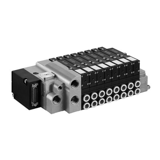
Page 70: Design
Made in Germany Power module Fig. 1: System architecture Design The HF03/HF02 valve system is composed of the following components depending on the order: Valve system with Right end plate for connecting the pneumatics centralized bus control Valve terminal in expansion stages for 1 to 16 valves... -
Page 71: Bus Coupler
AVENTICS | INTERBUS | R412005655–BDL–001–AB System Overview 3.1.1 Bus coupler X71 (BUS IN) “Rugged Line” connections: and X72 (BUS OUT) Fibre optic cable connection for the INTERBUS fieldbus with fibre optic cable for controlling the – valves and – the input/output modules. -
Page 72: 16-Position E24V-/16F-Ib Input Module
AVENTICS | INTERBUS | R412005655–BDL–001–AB System Overview 3.1.2 16-position E24V-/16f-IB input module M12x1 connections Module with 16 M12x1 inputs for connecting electrical sensor signals. Display 1 LED (green) IB DIA, INTERBUS diagnostic display 16 LEDs (yellow) D0 - D15, 1 LED per input, system... - Page 73 AVENTICS | INTERBUS | R412005655–BDL–001–AB System Overview NOTICE Wrong polarization The US1 and US2 voltages are not electrically isolated from one another. The GND connection for both voltages is bridged internally. If either one of the voltages has the wrong polarization, this can lead to a short circuit and can cause severe damage to the bus connection.
-
Page 74: Pm12A Power Module
AVENTICS | INTERBUS | R412005655–BDL–001–AB System Overview US1 and US2, low voltage The US1 supply voltage (for inputs and logics) is monitored at monitoring at 18.5 V 18.5 V. If the voltage falls below this value, an error signal is generated and is reported via LEDs and diagnostic information. -
Page 75: Function
AVENTICS | INTERBUS | R412005655–BDL–001–AB System Overview Function 3.3.1 Bus coupler INTERBUS standard The INTERBUS bus coupler conforms to the DIN EN 19258 standards for the INTERBUS. Please refer to this standard, the corresponding literature and the bus master's operating manual for details. -
Page 76: Pm12A Power Module
AVENTICS | INTERBUS | R412005655–BDL–001–AB Configuration 3.3.3 PM12A power module The bus coupler's restricted output can, in some circumstances, limit the number of outputs required. The power module supplies additional output modules via the POWER X10 connection on the power module. The power module is located... - Page 77 AVENTICS | INTERBUS | R412005655–BDL–001–AB Configuration POWER Fig. 2: The bus coupler's SMD S1 switch NOTICE The SMD switches can only be adjusted when the power supply is switched off, i. e. in a voltage-free state! Once the S1/1, S1/6 and S1/8 switches have been altered, it is important to reconfigure the bus as these switch positions affect the entire bus system.
- Page 78 AVENTICS | INTERBUS | R412005655–BDL–001–AB Configuration S1/8 switch baud rate The baud rate (data transfer speed) can be set to either 500 kBaud or to 2 MBaud. The baud rate setting on the S1/8 switch must be identical to the data transfer speed set by the master. If there is a...
-
Page 79: Valve System Configuration
AVENTICS | INTERBUS | R412005655–BDL–001–AB Configuration Explanations to Tab. 8: S1/2 switch: If the S1/2 switch is ON, the diagnostic message for the Collective message (PF) collective “peripheral error (PF)” signal will be released to the overload of valves, master. The diagnostic message will only be displayed on the outputs and inputs LED IB DIA if the diagnostic message is switched on. -
Page 80: Output Data Buffer Assignment
AVENTICS | INTERBUS | R412005655–BDL–001–AB Configuration 4.2.2 Output data buffer assignment A valve module is assigned either 2 bytes (up to 8 valves) or 4 bytes (up to 16 valves) in the output data buffer. This depends on the S1/1 switch setting. - Page 81 AVENTICS | INTERBUS | R412005655–BDL–001–AB Configuration Address assignment on a Table 10: Address assignment on a valve terminal valve terminal module Valve position Solenoid/ LED Byte Address with an AVENTICS- A0.0 compatible master A0.1 A0.2 A0.3 A0.4 A0.5 A0.6 A0.7 A1.0...
- Page 82 AVENTICS | INTERBUS | R412005655–BDL–001–AB Configuration Address assignment Table 11: Address assignment on a valve terminal on a valve terminal Valve position Solenoid/ LED Byte Address module with a A0.0 Siemens-compatible A0.1 master (high/low byte A0.2 exchanged) A0.3 A0.4 A0.5 A0.6...
-
Page 83: Input Data Buffer Assignment
AVENTICS | INTERBUS | R412005655–BDL–001–AB Configuration 4.2.3 Input data buffer assignment The input data from the valve system modules are placed in the input data buffer. Table 12: Input data buffer assignment Modules with inputs Number of input bytes assigned... -
Page 84: Installation
AVENTICS | INTERBUS | R412005655–BDL–001–AB Installation Installation Assembly 5.1.1 HF 03 mounting Dimensions The valve system can be mounted in any desired position with 4 screws (e. g. M6) or placed on a DIN rail, DIN EN 60715, 35 x 15. -
Page 85: Hf 02 Mounting
AVENTICS | INTERBUS | R412005655–BDL–001–AB Installation HF 02 mounting Dimensions The valve system can be mounted in any desired position with 4 screws (e. g. M6) or placed on a DIN rail, DIN EN 60715, 35 x 15. PG connection IO 1 A24V-/0.5A-IB... -
Page 86: Labeling
AVENTICS | INTERBUS | R412005655–BDL–001–AB Installation Labeling 5.3.1 Bus coupler Bus coupler Inscribe the address provided/used for the bus coupler on the bus coupler in the BTN field. POWER Fig. 5: Marking and identification of the bus coupler 5.3.2 I/O modules I/O modules The I/O connections are inscribed directly on the I/O modules. -
Page 87: Optical And Electrical Connections
AVENTICS | INTERBUS | R412005655–BDL–001–AB Installation Optical and electrical connections CAUTION Applied voltage Danger of injury from electric shocks. Only connect or disconnect the connections in a voltage- free state! When assembling and installing the “Rugged Line” connection, the guidelines from Phoenix Contact must be observed (e. -
Page 88: Logic And Load Supply
AVENTICS | INTERBUS | R412005655–BDL–001–AB Installation The incoming bus cable must be connected to X71 IN and the outgoing continuous bus cable to X72 OUT. If the VS bus coupler is the last station in the fieldbus connection, meaning that no continuing connection is required, the remote bus is connected to X71 IN and X72 OUT is equipped with a “Rugged Line”... - Page 89 AVENTICS | INTERBUS | R412005655–BDL–001–AB Installation NOTICE Wrong polarization All components are supplied from one 24 V source. The 24 V power supply must stem from a power supply unit which is electrically isolated according to DIN EN 60742, classification VDE 0551. The corresponding electrical circuits are thus SELV/PELV circuits in accordance with EN 60364.
-
Page 90: Connection Of I/O Modules
AVENTICS | INTERBUS | R412005655–BDL–001–AB Installation Power consumption for The power consumption should be set accordingly. When the supply voltage choosing suitable cable cross-sections, the cable length and the (bus coupler) emitted currents should be considered: Table 14: Power consumption on the bus coupler... -
Page 91: Input Assignment In The 16-Position E24V-/16F-Ib Input Module
AVENTICS | INTERBUS | R412005655–BDL–001–AB Installation 5.4.4 Input assignment in the 16-position E24V-/16f-IB input module The total current for all sensor supplies on one valve system must not exceed 2 A. Assignment of M12x1 Table 15: Input assignment in the 16-position E24V/16f-IB input module... -
Page 92: Pm12A Power Module Power Supply
AVENTICS | INTERBUS | R412005655–BDL–001–AB Installation Assignment of M12×1 Table 16: Output assignments in the 8-position A24V-/0.5A-IB output module connections on the 8-position A24V-/0.5A-IB Signal Assignment output module 1, 2 – Not connected PGND Ground for P24VA/P24VN Output Fed by P24VA from bus coupler or P24VN from power module –... - Page 93 AVENTICS | INTERBUS | R412005655–BDL–001–AB Installation POWER X10 Table 17: POWER X10 (power module) plug assignment plug assignment POWER X10 Assignment (power module) Functional earth See Fig. 9 P24VN Output voltage supply PGND Ground for P24VN – Not connected –...
-
Page 94: Establishing Optical And Electrical Connections
AVENTICS | INTERBUS | R412005655–BDL–001–AB Installation POWER X10 The power consumption should be set accordingly. When power consumption choosing suitable cable cross-sections, the cable length and the (power module) emitted currents should be considered: Table 18: POWER X10 power consumption (power module) -
Page 95: Testing, Start-Up, Diagnosis
AVENTICS | INTERBUS | R412005655–BDL–001–AB Testing, start-up, diagnosis Systems with input/output modules: 3. Connect the sensors to the input modules and the actuators to the output modules. 4. If a power module is present: connect the power supply cable to the power module's POWER X10. -
Page 96: Commissioning
AVENTICS | INTERBUS | R412005655–BDL–001–AB Testing, start-up, diagnosis Commissioning CAUTION Uncontrolled actuator movements when the pneumatics are switched on Danger of injury if the system is in an undefined state and the manual overrides are set to position “1”. Put the system in a defined state before switching it on. - Page 97 AVENTICS | INTERBUS | R412005655–BDL–001–AB Testing, start-up, diagnosis Table 21: Bus coupler diagnostic display, left LED group Signal Error Description Green US1 logics and sensor supply active (US1 > 18.5 V) Low voltage US1 logics and sensor supply (US1 < 18.5 V) Sensor supply overload (P24V ...
-
Page 98: Diagnostic Display On The 16-Position E24V-/16F-Ib Input Module
AVENTICS | INTERBUS | R412005655–BDL–001–AB Testing, start-up, diagnosis Table 22: Bus coupler diagnostic display, right LED group Signal Error Description The incoming fibre optic cable line is enabled or is not assigned Yellow The incoming fibre optic cable line is disabled or the system has no... -
Page 99: Diagnostic Display On The 8-Position A24V-/0.5A-Ib Output Module
AVENTICS | INTERBUS | R412005655–BDL–001–AB Testing, start-up, diagnosis 6.3.3 Diagnostic display on the 8-position A24V-/0.5A-IB output module The IB DIA and D0-D7 diagnostic LED on the 8-position output module show the diagnostic messages listed in the table below. This supplements the diagnostic display on the bus coupler and more precisely defines the cause of the error. - Page 100 AVENTICS | INTERBUS | R412005655–BDL–001–AB Testing, start-up, diagnosis Table 25: Local diagnostic displays on the bus coupler with centralized diagnostic messages on the control (CMD-SW or PLC) Event Signal L24V logic supply active Green – – P24V sensor supply active Green –...
-
Page 101: Voltage Diagnosis In The Status Byte
The order depends on the type of master used. A master compatible with AVENTICS systems reads the input diagnosis bytes in the order given below (with masters compatible with... - Page 102 AVENTICS | INTERBUS | R412005655–BDL–001–AB Testing, start-up, diagnosis Valve diagnosis The diagnosis identifies short circuit and interruption. The short circuit is identified in the controlled state, the interruption in the non-controlled state (preventive maintenance). The diagnosis of the valve (interruption/short circuit) is always reported and indicates that the valve is ready for operation (compare with readiness for operation of a frequency converter).
- Page 103 AVENTICS | INTERBUS | R412005655–BDL–001–AB Testing, start-up, diagnosis With a valve overload message, the valves should be assigned to the following bits: Table 31: Valve assignment with valve overload message Status Valve 1 No error Error Valve 2 Valve 3...
-
Page 104: Input Module Diagnosis In Input Data Range
The order depends on the type of master used. A master compatible with AVENTICS systems reads the input diagnosis bytes in the order given below (with masters compatible with Siemens, the high and low bytes are exchanged):... -
Page 105: Output Module Diagnosis In Input Data Range
The order depends on the type of master used. A master compatible with AVENTICS systems reads the input diagnosis bytes in the order given below (with masters compatible with Siemens, the high and low bytes are exchanged). -
Page 106: Example
AVENTICS | INTERBUS | R412005655–BDL–001–AB Testing, start-up, diagnosis 6.4.5 Example A valve system is equipped with 1 valve terminal module with 8 valve positions and 2 16-position input modules as well as 1 8-position output module. Table 37: Principle of physical assignment... - Page 107 AVENTICS | INTERBUS | R412005655–BDL–001–AB Testing, start-up, diagnosis Fig. 11: Principle of logical assignment Fig. 12: Process data...
-
Page 108: Identification (Id)
AVENTICS | INTERBUS | R412005655–BDL–001–AB Testing, start-up, diagnosis Table 40: Illustration of output data buffer Output data buffer Meaning Byte 0 Bit 0.0 ... 0.7 1 byte outputs valve terminal module Byte 1 Bit 1.0 ... 1.7 1 byte outputs valve terminal module Byte 2 Bit 3.0 ... -
Page 109: Conversion And Extension
AVENTICS | INTERBUS | R412005655–BDL–001–AB Conversion and extension Table 44: ID of the output module depending on the S1.6 switch position S1.6 Meaning Module type Data capacity No single bit diagnosis Local output module 189 (BD 1 bytes Single bit diagnosis... - Page 110 AVENTICS | INTERBUS | R412005655–BDL–001–AB Conversion and extension 2. Put the (additional) I/O module in place.Ensure that the gasket has been inserted properly and that the contacts have been plugged in. 3. Screw the I/O module tight (3 hexagon socket-head screws, DIN 912 M4, wrench width 3).
-
Page 111: Adding A Power Module Pm12A
AVENTICS | INTERBUS | R412005655–BDL–001–AB Conversion and extension Adding a power module PM12A See Fig. 14 Please note the following if expanding the valve system by a power module in order to be able to add additional output modules and provide a power supply: 2.5-3 Nm... -
Page 112: Exchanging The Bus Coupler
AVENTICS | INTERBUS | R412005655–BDL–001–AB Conversion and extension 1. Remove the left side cover from the last valve system I/O module (3 hexagon socket head screws, DIN 912 M4, wrench width 3). 2. Depending on the position in which the power module... - Page 113 AVENTICS | INTERBUS | R412005655–BDL–001–AB Conversion and extension 1. Disconnect the electrical connections from the bus coupler. 2. Remove the left side cover from the valve system's bus coupler (3 hexagon socket head screws, DIN 912 M4, wrench width 3).
-
Page 114: Replacing Fuses
AVENTICS | INTERBUS | R412005655–BDL–001–AB Conversion and extension Replacing fuses Before changing a fuse(s), please observe the following: CAUTION Applied voltage Danger of injury from electric shocks. Make sure the relevant system component is not under voltage or pressure before electrically connecting modules to the valve terminal. - Page 115 AVENTICS | INTERBUS | R412005655–BDL–001–AB Conversion and extension 2. Mount the bus coupler's front panel: – Connect the cable; the plug connection must lock into place. – The front panel should be reattached far enough to connect the tight plug contacts on both the multiple plugs.
-
Page 116: Characteristics, Service Parts And Accessories
AVENTICS | INTERBUS | R412005655–BDL–001–AB Characteristics, service parts and accessories Characteristics, service parts and accessories Characteristics 8.1.1 Bus coupler General Mounting orientation Protection class according IP 65 when assembled to EN 60529/IEC 529 Ambient temperature 0°C to +50°C Electrics Logic nominal voltage 24 V DC (–15%/+20%) -
Page 117: I/O Modules
AVENTICS | INTERBUS | R412005655–BDL–001–AB Characteristics, service parts and accessories 8.1.2 I/O modules General Protection class according IP 65 when assembled to EN 60529/IEC 529 Ambient temperature 0°C to +50°C Electrics Input Inputs DIN EN 61131-2 16 digital inputs, type 1 two wire proximity switch with idle current of max. -
Page 118: Spare Parts And Accessories
AVENTICS | INTERBUS | R412005655–BDL–001–AB Characteristics, service parts and accessories Spare parts and accessories 8.2.1 Bus coupler Order code Order number VS bus coupler INTERBUS LWL DG RM65M-DG-IB-L R412005819 Accessories Supplier Plug connector/“Rugged Line” connection cable Phoenix Contact “Rugged Line” dummy plug Delivery incl. - Page 119 AVENTICS | INTERBUS | R412005655–BDL–001–AB Characteristics, service parts and accessories...
- Page 120 German language. R412005655–BDL–001–AB/10.2014 Subject to modifications. © All rights reserved by AVENTICS GmbH, even and especially in cases of proprietary rights applications. It may not be reproduced or given to third parties without its consent.
Need help?
Do you have a question about the HF02 and is the answer not in the manual?
Questions and answers