Table of Contents
Advertisement
Quick Links
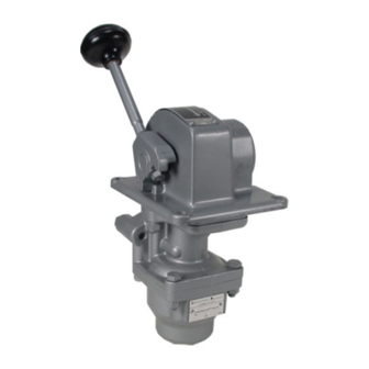
HE - 2 TYPE CONTROLAIR
FIG. 1 EXTERIOR VIEW
INSTALLATION! Do not attempt to install, operate or repair these
devices without proper training in the technique of working on pneu-
matic or hydraulic systems and devices, unless under trained supervi-
sion.
Compressed air and hydraulic systems contain high levels of stored
energy. Do not attempt to connect, disconnect or repair these products
when a system is under pressure. Always exhaust or drain the
pressure from a system before performing any service work. Failure to
do so can result in serious personal injury.
MOUNTING! Devices should be mounted and positioned in such a
manner that they cannot be accidentally operated.
DESCRIPTION OF MODELS
The HE-2 type CONTROLAIR Valves are handle operated units
consisting of one 3-way directional side valve, and a 3-way pressure
graduating portion. The directional side valve is arranged to supply
inlet pressure to a separate delivery line. The pressure graduating
portion is arranged to increase, decrease, or maintain graduated air
pressure to a second separate delivery line.
In "off" position both delivery lines are exhausted. Handle movement
from "off" position actuates the graduating pressure to a delivery line.
The first 10 degrees of handle travel from "off" position to "clutch"
position opens the side valve to direct inlet supply pressure to a
second delivery line. Further movement of handle past 10 degrees to
full travel position, or 92 degrees, continues to activate the pressure
graduating valve to deliver graduated pressure which increases in
proportion to the amount of handle movement from neutral. The
maximum pressure obtained at full handle travel depends on the value
of the control spring installed.
There are three models identical in function, but different in handle
operating charactistics.
HE-2-X CONTROLAIR Valve - Handle is spring returned to the
"clutch" or off position from all other positions in the handle travel arc,
EXCEPT Part No. R434002110 (P -062026-00001) which returns han-
dle to "off"
position from all other positions. WARNING: The possi-
bility of handle returning to "off" position does exist in all HE-2-X mod-
els in positions from clutch through full travel position when released.
HE-2-LX CONTROLAIR Valve - Handle is spring returned to "clutch"
or "off" position from all other positions in handle travel arc, EXCEPT
there is mechanical detent to handle the handle at the maximum
pressure position.
SM-800.6511
Service Information
WARNING:
INSTALLATION & MOUNTING
The user of these devices must conform to all
applicable electrical, mechanical, piping and other
codes in the installation, operation or repair of
these devices.
MODELS
®
VALVE
CLUTCH
OFF
PRESSURE vs. LEVER TRAVEL
WARNING! Increased friction due to dirt and wear may
caused handle not to return to clutch position from lower end
of travel arc.
HE-2-FX CONTROLAIR Valve - Handle is equipped with a
friction brake that will hold the handle in any position selected
in the handle travel arc. The brake is internally adjustable.
TABLE OF CONTENTS
Description of Models..............................................1
Graphical Symbols..................................................1
Technical Data.......................................................2
Installation.............................................................2
Maintenance and Repair..........................................2
Outline Dimensions.................................................3
Description of Operation.....................................4 & 5
Identity Schedule..............................................6 & 7
Exploded Views.................................................... 8
Parts List............................................................. 9
Assembly Section Views..................................10 & 11
Repair Kit List.......................................................12
Maintenance and Repair Instructions........................ 13
Adjustment and Testing
Graduated Output Adjustment..........................13
Preload Setting Adjustment.............................13
Cam Dog Adjustment.....................................13
Side Lever Adjustment....................................13
Friction Brake Adjustment...............................13
Testing:
Function......................................................14
Pressure Range............................................14
Leakage.....................................................14
Flow Capacity.............................................14
Response...................................................14
Mechanical Detent........................................14
Test Setup......................................................15
Warnings and Warranties........................................16
FULL
TRAVEL
PAGE
Advertisement
Table of Contents

Related Manuals for Aventics CONTROLAIR HE-2


Summary of Contents for Aventics CONTROLAIR HE-2
-
Page 1: Table Of Contents
® HE - 2 TYPE CONTROLAIR VALVE Service Information CLUTCH FULL TRAVEL WARNING: INSTALLATION & MOUNTING The user of these devices must conform to all applicable electrical, mechanical, piping and other codes in the installation, operation or repair of these devices. FIG. -
Page 2: Technical Data
INSTALLATION AND GENERAL MAINTENANCE AND REPAIR RECOMMENDATIONS A major overhaul is recommended at one million INSTALLATION cycles. However, where frequency of use is such that Before installing the CONTROLAIR Valve, all air lines in the it would require more than two years to obtain one system should be blown clean to remove any moisture, dirt, million cycles, the valve must be overhauled at the or harmful contamination. - Page 3 ® HE-2-TYPE CONTROLAlR Valve 4.88 Pipe Bracket Side of View 4.44 4.00 1.94 2.28 .38R. 1.50R 1.50R 2.50 2.38 4.69 CLUTCH 7.38 4.69 3.50 1.00R. 1.00R. PANEL OPENING DIMENSIONS - INSTALLATION INSTRUCTIONS 1. Panel thickness must not exceed 0.25” to clear pipe bracket and cover flange.
-
Page 4: Description Of Operation
DESCRIPTION OF OPERATION Note in the diagrammatic that supply The HE-2 CONTROLAIR Valve will pressure is connected to port (2) and this supply automatically compensate for downstream air pressure is directed to the side control valve and pressure changes in the graduated pressure the graduating pressure control valve. - Page 5 DIAGRAMMATIC VIEW Valve Symbol ME-2 Controlair Valve Clutch Full Travel Adjusting Screw Dual Cam Side Valve (3-Way) Inlet & Exhaust Valve Unit Diaphragm Supply Valve Sensing Port Orifice Exhaust Valve Range Control Spring LEGEND PIPE BRACKET 2 - SUPPLY-IN Exhaust Port 8 - GRADUATED-DELIVERY Adjust Screw 1 - SIDE VALVE-DELIVERY...
-
Page 6: Identity Schedule
IDENTITY SCHEDULE Control New Control Old Control New Cam Old Cam New Valve Old Valve Remarks Model Pressure Part No. Part No. Spring P/N Spring P/N Portion P/N Portion P/N Portion P/N Portion P/N Range (PSI) R431002937 P -051692- 0-65 R431003732 P -05542-00000 R431002940 P -051694- R4313843 P -05584-... - Page 7 ® CONTROLAIR VALVE PORTIONS Clutch Full Travel Cam Portion Complete See Identity Schedule 1/4-18 NPT - 4 Holes Pipe Bracket Portion Part No. R431006914 (Old Valve Portion Complete Part No. P -066890- See Identity Schedule 00000) Ref. Items 1,2,3 #3 Port Plugged Page 8 &...
-
Page 8: Exploded Views
EXPLODED VIEW MODEL HE-2 ® HE-2-X CONTROLAIR ® ® CONTROLAIR VALVES HE-2-LX CONTROLAIR ® HE-2-FX CONTROLAIR Stainless Steel Handle Brake Assy. Part No. R43100130 (-850182-00000) NOTE: See Page 8 & 9 for part numbers See page 12 for repair kits Matched/Lapped set of Items 34-41 are in Kit, R431003892 (P -055687-00000) Pg 12 P/N (R431006914) -
Page 9: Parts List
® HE-2 CONTROLAIR VALVE PARTS LIST HE-2-X HE-2-X HE-2-LX HE-2-FX REF. QTY. DESCRIPTION HE-2-FX P -066625 P -051614* P -051692* P -062026* P -051612* New P/N Old P/N New P/N Old P/N New P/N Old P/N New P/N Old P/N New P/N Old P/N Bracket, Pipe... - Page 10 ® HE-2 CONTROLAIR VALVE PARTS LIST (Continued) HE-2-X HE-2-X HE-2-LX HE-2-FX REF QTY. DESCRIPTION HE-2-FX P -066625* P -051614* P -051692* P -062026* P -051612* New P/N Old P/N New P/N Old P/N New P/N Old P/N New P/N Old P/N New P/N Old P/N Nut, 9/16-18...
- Page 11 ® HE-2-X & HE-2-LX CONTROLAIR VALVE ASSEMBLY Latch Assemble Spring w/ Loctite- Omitted on TL-242 H-2-X Models Port No. 3 Plugged Section A-A Partial Section B-B Section C-C Partial Section D-D Partial Section E-E Page 11...
- Page 12 ® HE-2-FX CONTROLAIR VALVE ASSEMBLY Assemble w/ Loctite TL242 Port No. 3 Plugged Partial Section 3-B Section A-A HE-2-FX Model Only Friction Brake Section C-C Page12...
- Page 13 ® REPAIR KITS FOR HE-2 CONTROLAIR VALVE NEW PART NO. OLD PART NO. QUANTITY DESCRIPTION PER VALVE R431003895* P -055687-00000 MINOR GRADUATING VALVE PORTION - REPAIR KIT (Includes Items 34, 35, 36, 37, 38, 39, 41) See Note 1 R431004005 P -057136-00000 MAJOR GRADUATING VALVE PORTION - REPAIR KIT (Includes Items 2, 3, 18, 29 and Kit...
-
Page 14: Adjustments
MAJOR REPAIR AND MAINTENANCE ADJUSTMENTS MAJOR REPAIR AND MAINTENANCE INSTRUTION ADJUSTMENTS ® When it is determined that the CONTROLAIR Valve requires Screw (4) varies the graduated output pressure setting. Screw shop repairs (see page 2 for GENERAL MAINTENANCE AND (23) adjusts the opening of the side valve, and screw (19) REPAIR RECOMMENDTIONS) the following general instruc- aligns the follower (18) with cam (61). -
Page 15: Function
TESTING AND TEST SET-UP TESTING VALVE ® After any repair or adjustment, the HE-2 CONTROLAIR Valve Moving handle quickly from full travel position to “off” position should exhaust volume (1) within time limits should be tested using procedures and test arrangements de- shown in Table I. - Page 16 HE-2 TEST ARRANGEMENT DIAGRAM NOTES: 1. TASKMASTER timing volume, part number R434002899 (TM-005887-00225), can be used for the volumes indicated. 2. The supply air lines to the valves and delivery lines must be full size as shown. Line length must not exceed 3 ft. (1 meter) between the supply valve and port (2), or between ports (1), and (8), and the test volume.
- Page 17 No charge will be made for labor with respect to defects covered by this Warranty, provided that the work is done by AVENTICS or any of its authorized service facilities.
- Page 18 SM-800.6511/May 2014 Subject to change. Printed in United States. AVENTICS Corporation. This document, as well as the data, specifications, and other information set forth in it, are the exclusive property of AVENTICS. It may not be reproduced or given to third parties without its consent.
Need help?
Do you have a question about the CONTROLAIR HE-2 and is the answer not in the manual?
Questions and answers