Table of Contents
Advertisement
Quick Links
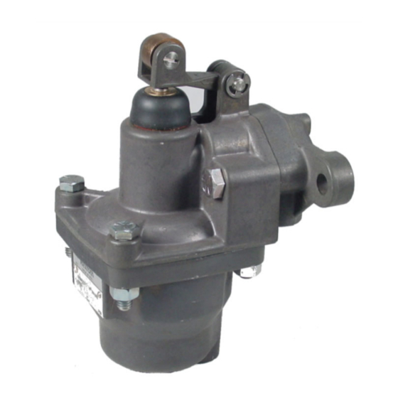
H-3, H-3-G & SH-3 CONTROLAIR
DESCRIPTION OF MODEL
The H-3 TYPE CONTROLAIR Valves are 3-way
pneumatic pressure graduating valves. The operator
portion is equipped with a cam roller which can be
operated by another cam or similar mechanical
operator. The roller actuates the pressure graduating
potion to increase, decrease, or maintain graduated air
pressure to a separate delivery line.
In "release" position the delivery line is connected to
exhaust, except preload type. From "release" position,
force down on the roller actuates the graduating portion
to deliver graduated pressure to a delivery line
according to the value of control spring being used.
The roller is spring returned from all positions.
WARNING: INSTALLATION AND
MOUNTING
The user of these devices must conform to all applicable
electrical, mechanical, piping and other codes in the
installation, operation or repair of these devices.
INSTALLATION! Do not attempt to install, operate or
repair these devices without proper training in the
technique of working on pneumatic or hydraulic systems
and devices, unless under trained supervision.
Compressed air and hydraulic systems contain high
levels of stored energy. Do not attempt to connect,
disconnect or repair these products when a system is
under pressure. Always exhaust or drain the pressure
from a system before performing any service work.
Failure to do so can result in serious personal injury.
MOUNTING! Devices should be mounted and positioned
in such a manner that they cannot be accidentally
operated.
SM-800.6515
Service Information
Table of Contents
Technical Data .............................................. 2
Installation ..................................................... 2
Maintenance and Repair ............................... 2
Outline View .................................................. 3
Description of Operation ................................ 4
Symbol .......................................................... 4
Diagrammatic & Assembly Views .................. 4
Identity Schedule ........................................... 5
Exploded Views ............................................. 6
Parts List ....................................................... 7
Repair Kit List ................................................ 8
SH-3 Version ................................................. 9-10
Maintenance and Repair Instructions ............ 11
Adjustment and Repair Instructions .............. 11
Testing:
Function ................................................. 12
Pressure Range ..................................... 12
Leakage ................................................. 12
Flow Capacity......................................... 12
Response ............................................... 12
Test Set-up ............................................ 12
Test Diagram ................................................. 13
Warnings and Warranties .............................. 14
®
VALVE
Page
.................................. 1
Advertisement
Table of Contents

Related Manuals for Aventics CONTROLAIR H-3


Summary of Contents for Aventics CONTROLAIR H-3
-
Page 1: Table Of Contents
® H-3, H-3-G & SH-3 CONTROLAIR VALVE Service Information DESCRIPTION OF MODEL The H-3 TYPE CONTROLAIR Valves are 3-way pneumatic pressure graduating valves. The operator portion is equipped with a cam roller which can be operated by another cam or similar mechanical operator. -
Page 2: Technical Data
Installation and General Maintenance Recommendations General Maintenance and Repair Installation ® Before installing the CONTROLAIR Valve, all air lines Maintenance periods should be scheduled in accordance with in the system should be blown clean to remove any frequency working environment moisture, dirt, or harmful contamination. -
Page 3: Outline View
® H-3 CONTROLAIR VALVES OUTLINE DIMENSIONS Adjustable CAM Roller 0.031” Eccentric for total Roller adjustment of 0.062” to obtain 2.531” “A” Dim. Page 3... -
Page 4: Description Of Operation
DESCRIPTION OF OPERATION DIAGRAMMATIC VIEW VALVE FUNCTION CAM Roller Adjustment Outlet Exhaust CAM Roller Assembly Inlet Inlet & Exhaust Valve Unit In released position, the supply valve is closed to Supply Valve supply pressure and “out” port is open to exhaust. Note in the diagram, when the roller is forced down to increase pressure, it pushes down the pressure control plunger, closing the lower exhaust valve and... -
Page 5: Identity Schedule
IDENTITY SCHEDULE H-3 COMPLETE CONTROL SPRING & COLOR CODE "A" DIMENSION NEW VALVE OLD VALVE MAXIMUM DELIVERY CONTROL* CONTROL* OUT PRES- PRESSURE PORTION PORTION MAXIMUM NOTES SURE +5/-0 RANGE COMPLETE COMPLETE NORMAL LAPPED PRES- NEW PART NEW PART OLD PART NO. NUMBER NUMBER OLD PART NO. -
Page 6: Exploded Views
EXPLODED VIEW Notes: 1. See page 7 for part numbers. 2. See page 8 for repair kits. 3. Matched/lapped set of items 13 and 14, and 8 - 12 are in kit, Part Number R431003895 page 8. Pipe Bracket Valve Control Portion Complete (See Identity Schedule) Page 6... -
Page 7: Parts List
PARTS LIST H-3 & H-3-G NEW PART REF. QTY. DESCRIPTION OLD PART NO. Adjusting screw R431006770 P -066209-00000 Spring housing w/nut R431006822 P -066488-00002 Spring housing H-3-G R431002975 P -052199-00000 Nuts, 5/16"-18 R431002419 P -049901-00020 Spring seat R431000036 -526347-00000 Control spring (See Identity Schedule, page 5) Body, w/2 studs R431000045... -
Page 8: Repair Kit List
REPAIR KITS QTY. PER NEW PART NO. OLD PART NO. DESCRIPTION VALVE MINOR GRADUATING VALVE PORTION Repair Kit R431003895 P -055687-K0000* (Includes Items 8, 9, 10, 11, 12, 13, 14) See note 1 MAJOR GRADUATING VALVE PORTION Repair Kit R431004887 P -059028-K0000 (Includes Items 15, 16, 17, 18, and Kit R431003895) LEVER Repair Kit... -
Page 9: Version
® SH-3 CONTROLAIR VALVE The SH-3 has a larger diaphragm for minimum hysteresis, better graduation and increased sensitivity. See page 10 for additional dimensional information. Repairs for complete devices P -066183-00001 P -066183-00002 *P -066183-00003 *P -066183-00004 *P -066183-00006 P -066183-00008 P -066183-00009 P -066183-00015 P -066184-00002... - Page 10 ® SH-3 CONTROLAIR VALVE ‘A’ (Factory Setting) New Valve Old Valve Part Number Part Number Full Exhaust Ex. Valve Closed 0 psi Delivery Max. Delivery — P –063150-00001 2.750” 2.625” Approx. psi @2.125 Lever Travel ‘A’ (Factory Setting) New Valve Old Valve Part Number Part Number...
-
Page 11: Maintenance And Repair Instructions
MAJOR REPAIR AND MAINTENANCE, ADJUSTMENTS Schedule (page 5). This dimension varies according to the pressure Major Repair and Maintenance Instruction range of the control spring used in the valve. With the roller in this position, the air gauge should be the maximum delivery pressure (+5/-0 psi). -
Page 12: Function
TESTING AND TEST SET-UP ® After repair or adjustment, the H-3 CONTROLAIR Valve A. On all valves with spring ranges less than 100 psi should be tested using procedures and test arrangements (6.9 bar), set supply line pressure to 100 psi (6.9 as described in this section. -
Page 13: Test Diagram
#6 SINGLE BRAID HOSE OPTIONAL: REQUIRED FOR LOW SPRING RANGE VALVES ONLY. CLEAN, DRY, CHEMICAL FREE AIR SUPPLY 200 PSIG MAXIMUM (OR 20 PSIG ABOVE MAXIMUM DELIVERY PRESSURE OF ANY VALVE TESTED). PD-020031-00091 RECOMMENDED: AVENTICS New P/N R432016359 (Old P/N PR-007816-00010) Page 13... -
Page 14: Warnings And Warranties
No charge will be made for labor with respect to defects covered by this Warranty, provided that the work is done by AVENTICS or any of its authorized service facilities. - Page 15 SM-800.6515/May 2014 Subject to change. Printed in United States. AVENTICS Corporation. This document, as well as the data, specifications, and other information set forth in it, are the exclusive property of AVENTICS. It may not be reproduced or given to third parties without its consent.
Need help?
Do you have a question about the CONTROLAIR H-3 and is the answer not in the manual?
Questions and answers