Table of Contents
Advertisement
Quick Links
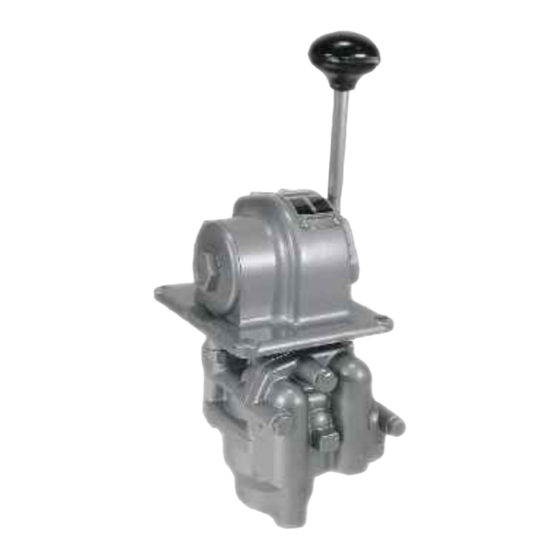
DESCRIPTION OF MODELS
The HG-2 type CONTROLAIR valves are handle
operated units consisting of one 3-way directional
side valve and a 3-way pressure graduating
portion. The directional side valve is arranged to
supply full supply pressure to two separate
delivery lines. The pressure graduating portion is
arranged to increase, decrease, or maintain
graduated air pressure to a second separate
delivery line.
In neutral position both delivery lines are
exhausted.
Handle movement either side of
neutral position actuates the graduating portion to
deliver graduated pressure to one of the delivery
lines as the handle is moved to full travel position.
The side valve is operated in only one direction of
handle travel movement from neutral position. A
movement of 10 degrees from neutral position
opens the 3-way side valve and directs supply
pressure to a delivery line. Further movement
past 10 degrees to full travel position (46
degrees) continues to actuate the side valve
delivery supply pressure to the delivery lines, and
continues to activate the pressure graduating
valve to deliver graduated pressure to a second
delivery line which increases in proportion to the
amount of handle movement from neutral. The
maximum graduated pressure obtained at full
handle travel depends on the value of the control
spring installed.
MODELS
The only model of the HG-2 type valve is the HG-
2-FX CONTROLAIR Valve.
equipped with a friction brake that will hold the
handle in any position selected in the handle
travel arc. The brake is internally adjustable.
SM-800.6512
HG-2 TYPE CONTROLAIR
SERVICE INFORMATION
The handle is
®
VALVE
TABLE OF CONTENTS
PAGE
1
2
2
2
2
3
4
5
6
7
8
9-10
11
12
12
12
12
12
12
12
13
Advertisement
Table of Contents

Related Manuals for Aventics CONTROLAIR HG-2


Summary of Contents for Aventics CONTROLAIR HG-2
-
Page 1: Table Of Contents
HG-2 TYPE CONTROLAIR ® VALVE SERVICE INFORMATION DESCRIPTION OF MODELS The HG-2 type CONTROLAIR valves are handle operated units consisting of one 3-way directional side valve and a 3-way pressure graduating portion. The directional side valve is arranged to supply full supply pressure to two separate delivery lines. -
Page 2: Warnings
Installation and General Maintenance Recommendations WARNING: INSTALLATION All valves must be visually inspected for wear given “in System” operating and MOUNTING performance and leakage test at least once a year. If these visual observations indicate valve repair is required, the valve must be removed The user of these devices must conform to all immediately and repaired. -
Page 3: Outline Dimensions
HG-2 TYPE CONTROLAIR ® VALVE OUTLINE VIEW Page 3... -
Page 4: Descriptions Of Operation
Description of Operation For HG-2 Controlair ® Valve Note in the diagrammatic view that supply The value of the pressure delivered to the outlet pressure is connected to port (2) and this supply port is proportional to the pressure graduating pressure is directed to the pressure-graduating portion plunger movement. -
Page 5: Maintenance And Repair
Repair and Maintenance Instructions Repair and Maintenance Instructions Move the control handle to a maximum pressure position. With 3/32” Allen Wrench, back out adjusting screws Items ® When it has been determined that the Controlair Valve #23 of the operated lever #20 just far enough to open the requires repairs, the following general instructions are exhaust valve so that gauge in the output line starts to recommended. -
Page 6: Graphical Symbol
DIAGRAMMATIC VIEW Valve Symbol ® HG-2 CONTROLAIR VALVE NEUTRAL FULL TRAVEL FULL TRAVEL DUAL CAM FULL TRAVEL SIDE VALVE (3-Way) INLET & EXHAUST VALVE UNIT DIAPHRAGM SUPPLY VALVE SENSING PORT ORIFICE LEGEND - PIPE BRACKET EXHAUST VALVE 2 - SUPPLY-IN RANGE CONTROL SPRING 8 - GRADUATED-DELIVERY 1 - SIDE VALVE-DELIVERY... -
Page 7: Identity Schedule
HG-2 IDENTITY SCHEDULE Control Control Model Part Part Spring Spring Number Number Part Part Number Number —- P -066654-00001 R431003732 P -055442-00000 HG-2-FX —- P -066654-00002 R431000043 -526749-00000 **Valve **Valve Model Portion Portion Portion Portion Part Part Part Part Number Number Number Number... -
Page 8: Exploded View
EXPLODED VIEW MODEL HG-2 CONTROLAIR ® VALVES Brake Assy. Part No. R431001302 (-850187-00000) NOTE: See Page 8 & 9 for part numbers See page 12 for repair kits Matched/Lapped set of Items 34-41 are in Kit. R431003892 (P -055687-00000) Pg. 12 P/N (R431006913) P -066890-00000 Pipe Bracket Portion Complete Ref. -
Page 9: Part List
HG-2 CONTROLAIR VALVE ® REF. QTY. DESCRIPTION HG-2-FX P -066654-00001* New P/N Old P/N Bracket, Pipe R431006882 P -066812-00005 Strainer, Port R431006895 P -066849-00000 Gaskets, Port R431006889 P -066823-00000 Screw, 5/16 x 2 1/4 R431002440 P -049902-00048 Body, Complete R431002869 P -051112-00002 Bushed including. - Page 10 HG-2 CONTROLAIR VALVE ® PARTS LIST (Continued) REF. QTY. DESCRIPTION HG-2-FX P -066654-00002 New P/N Old P/N Nut, 9/16-18 See Kits See Kits Ring, 11/16 - “O” Ring See Kits See Kits Screw Spline Hex. Adjustment R431006770 P -066209-00000 Seat Exhaust Valve See Kits See Kits Screw, 5/16-18...
-
Page 11: Repair Kit
Repair Kits for HG-2 Controlair ® Valves New Part No. Old Part No. Quantity Description Per Valve R431003895 P -055687-00000 Minor Graduating Valve Portion-Repair Kit Note 1 Includes items 25, 29, 34, 35, 36, 37, 39 & 42 R431004005 P -057136-00000 Major Graduating Valve Portion-Repair Kit Note 1 Includes items 2, 3 &... -
Page 12: Testing
Testing and Test Set-Up Testing delivery line (1) and hold in that position. After any repair or adjustments, the HG-2 Closed valve in supply line to port (2) and Controlair Valve should be tested using the valve and valve in port (1) delivery line to following procedures and test arrangements isolate the graduating valve. -
Page 13: Test Diagram
Test Arrangement Diagram Notes: ® 1. AVENTICS Taskmaster Timing Volumes, part number R431002899 (TM-058887-00225) can be used for the volumes indicated. 2. The supply air line to the valve and the delivery lines must be full size as shown. Line must not exceed 3 ft. - Page 14 No charge will be made for labor with respect to defects covered by this Warranty, provided that the work is done by AVENTICS or any of its authorized service facilities.
- Page 15 Slv1-8.QQ.65:12/May 2QT4 Sub1ec:ttn c:hange. Printed in United States. AVENTICS Carparatian This dac:urnent. as well as the data. spec:ific:atians. and atherinfurmatian setfurth in it are the ED\Clusive property at AVEl"-JTICS. It may natb.e reproduced ar given ta third parties withaut its can sent...
Need help?
Do you have a question about the CONTROLAIR HG-2 and is the answer not in the manual?
Questions and answers