BWI Eagle AIR-EAGLE SR PLUS Product Information Bulletin
Hide thumbs
Also See for AIR-EAGLE SR PLUS:
- Manual (10 pages) ,
- Quick start manual (7 pages) ,
- Product information bulletin (5 pages)
Advertisement
Quick Links
AIR-EAGLE
2.4 GHz RF Transceiver
MODEL 36-6000-DC
DESCRIPTION
The A
-E
SR PLUS RF T
IR
AGLE
RANSCEIVER IS
transmit and receive unique signals from another transceiver located up to
600 feet away. This model comes equipped with three contact inputs and
two high current SPDT relay outputs. This allows the user to not only
transmit information out but receive a confirming signal back that the
operation was performed. The Air-Eagle SR PLUS TRX is user-
programmable for up to eight network frequencies to allow multiple
systems to operate simultaneously in the same area and utilizes spread-
spectrum technology and provides the utmost security and reliability even
in the noisiest RF environments.
INSTALLATION
DISCONNECT Power from all equipment before installation.
1.
Mount the control unit in a convenient location.
2.
Install control wiring to terminal strip.
3.
Make desired relay, channel code and frequency selections using
instructions on page 2.
4.
Attach antenna to TNC connector located on the right side on the
enclosure.
5.
Connect DC power to the proper terminals in your control circuit.
PC BOARD SET-UP INFORMATION
Make the following connections on the PC Board Terminal Strip (TER1)
TERMINAL STRIP WIRING (TER1)
Terminal 1
Negative (-) 9-36VDC INPUT
Terminal 2
Positive (+) 9-36VDC INPUT
Terminal 3
CH1 Dry Contact Input (Common)
Terminal 4
CH1 Dry Contact Input
Terminal 5
CH2 Dry Contact Input (Common)
Terminal 6
CH2 Dry Contact Input
Terminal 7
CH3 Dry Contact Input (Common)
Terminal 8
CH3 Dry Contact Input
Terminal 9
CH1 Relay N/O
Terminal 10
CH1 Relay C
Terminal 11
CH1 Relay N/C
Terminal 12
CH2 Relay N/O
Terminal 13
CH2 Relay C
Terminal 14
CH2 Relay N/C
105 Bonnie Drive
Butler, PA 16002
724-283-4681
724-283-5939 (fax)
www.bwieagle.com
®
SR PLUS
a dual I/O unit designed to
PRODUCT INFORMATION
BULLETIN
Dimensions (with mounting plate) 6.3" L x 4.8" W x 2.3" H
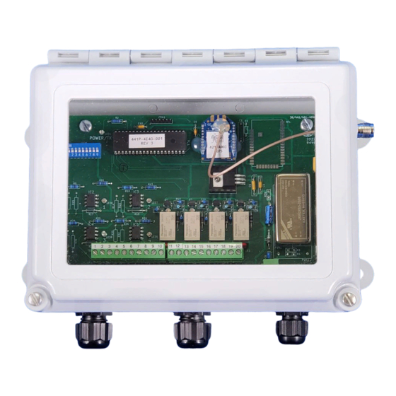
CONTROLS & INDICATORS
Illuminates Green when power is applied,
POWER/TX LED
changes to Red when transmitting.
Green LED illuminates continuously while relay
LED1
#1 is energized
Green LED illuminates continuously while relay
LED2
#2 is energized
CH1 – CH3 Dry
Transmit individual RF codes to the remote
Contact Inputs
transceiver
REL1 & REL2
Two SPDT output control relays
RF Module that transmits/receives data for
RF1
corresponding unit
Advertisement

Related Manuals for BWI Eagle AIR-EAGLE SR PLUS


Summary of Contents for BWI Eagle AIR-EAGLE SR PLUS
- Page 1 SPDT relay outputs. This allows the user to not only transmit information out but receive a confirming signal back that the operation was performed. The Air-Eagle SR PLUS TRX is user- programmable for up to eight network frequencies to allow multiple...
- Page 2 DIMENSIONS AIR-EAGLE ® SR PLUS 2.4 GHz RF Transceiver MODEL 36-6000-DC RELAY, CHANNEL CODES & FREQUENCY SETTINGS The unit is shipped from the factory with SEL1 switches in the open positions. The relays will operate as maintained momentary, the unit is transmitting &...
- Page 3 Used to increase range in both non line of sight and line of sight not allow the exclusion of implied warranties so this limitation may not applications. - Contact BWI Eagle for recommendations apply to you. To obtain warranty service, contact BWI Eagle for a return 2.4GHz Thru-Hole Mount Mobile Antenna 49-2201 material authorization.