Table of Contents
Advertisement
Centrometal d.o.o. - Glavna 12, 40306 Macinec, Croatia, tel: +385 40 372 600, fax: +385 40 372 611
TECHNICAL INSTRUCTIONS
for installation, use and maintenance
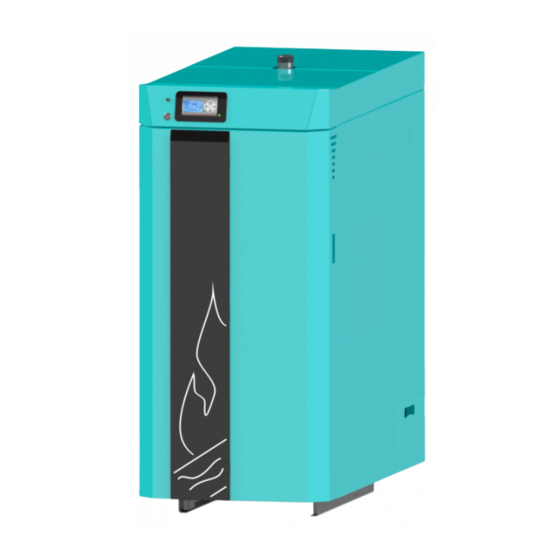
of hot water boiler
THE FIRST START-UP MUST BE DONE BY AUTHORIZED PERSON
OTHERWISE PRODUCT WARRANTY IS NOT VALID
TUBT-C-01-2020-ENG
HEATING TECHNIQUE
BioTec-C 25/31/35/45
Advertisement
Table of Contents

Subscribe to Our Youtube Channel
Related Manuals for Centrometal BioTec-C Series


Summary of Contents for Centrometal BioTec-C Series
- Page 1 HEATING TECHNIQUE Centrometal d.o.o. - Glavna 12, 40306 Macinec, Croatia, tel: +385 40 372 600, fax: +385 40 372 611 TECHNICAL INSTRUCTIONS for installation, use and maintenance of hot water boiler THE FIRST START-UP MUST BE DONE BY AUTHORIZED PERSON...
- Page 2 Important These instructions are an integral part of this product. All rights reserved. Reproduction of content of this document and transfer to third parties is not allowed without written approval from manufacturer. Make sure the instructions are always with the device, even if its sale/transfer of another owner to the user or staff authorized for maintenance or repairs to consult.
-
Page 3: Technical Data
Technical data TECHNICAL DATA TYPE BioTec-C Nominal heat output (kW) Boiler class Required chimney underpressure 0.08 (mbar) Water amount in boiler Exhaust gas temp. at nominal heat output 0 -180 (°C) Exhaust mass flow at nominal heat output 0,019 0,020 0,022 0,027 (kg/s) - Page 4 Dimensions, basic parts KA TO BioTec-C 25 KA TO BioTec-C 31 / 35 KA TO BioTec-C 45 Boiler dimensions BioTec-C 25 BioTec-C 31 BioTec-C 35 BioTec-C 45 Depth 1400 1445 1445 1385 Width Height 1375 1420 1420 1615 (C1) Height 1040 1075 1075...
-
Page 5: Basic Parts
Basic parts BioTec-C 25 Detail 1. - Flue gas tube cleaning lever Detail 2. - Lower opening lid for flue gas chamber cleaning BioTec-C 31/35/45 Detail 1. - Flue gas tube cleaning lever Lower opening lid for Detail 2. - flue gas chamber cleaning LEGEND: Secondary air intake... - Page 6 General, Characteristics 1.0. GENERAL Steel hot water boilers BioTec-C, nominal heat output 25 to 45 kW, are designed for wood log firing, for heating of small and middle sized premises. The wood gasification principle enables a complete fuel burning. Logs up to 550 mm long can be inserted into the large combustion chamber.
-
Page 7: Delivery Package
Wood gasification, delivery package, additional equipment 1.2. WOOD GASIFICATION COMBUSTION PROCESS Combustion process is carried out in double combustion chamber in several phases. After filling the upper chamber with logs, glow dry the logs, and at temperature 100÷300°C logs are beeing gasified. The gases created in such process are mixed with the oxygen from air and burn out completely with high temperature. - Page 8 Additional equipment, additional equipment positioning and assembly For closed heating systems: - Thermal safety valve - Safety-airvent group (2,5 bar) - Expansion vessel for closed heating systems (size according the volume of heating installation, including buffer tank volume) For open heating systems: - Open expansion vessel (size according the volume of heating installation, including buffer tank volume) NOTE: this equipment is not in standard boiler delivery...
- Page 9 Installation of delivered parts 2.1. INSTALLATION OF DELIVERED PARTS FORBIDDEN! ALLOWED! 1. The boiler is supplied on a wooden stand (pedestal) protected by a wooden box and PVC foil. The wood box and the PVC foil must be removed before/when placing the boiler to the position of installation. 2.
- Page 10 Installation of delivered parts BioTec-C is delivered on wooden pallet. After the boiler is removed from wooden pallet, should be positioned in the boiler room (see point 2.0.). Install base protection with stone wool under the boiler as shown in figure 2.a. In upper chamber of the boiler are delivered (figure 2.b): 1.
-
Page 11: Connection To The Chimney
Connection to the chimney 3.0. CONNECTION TO THE CHIMNEY Properly dimensioned and built chimney is the precondition for a safe and reliable operation of the boiler and economic heating. The chimney has to be good insulated, gas-proof and smooth. On the lower part of the chimney, a cleaning door has to be built in. - Page 12 Connection to the chimney, calibrating of the chimney At connecting a boiler to the chimney, flue gas tubes and elbows must not pass behind the fan since in that case the cleaning and maintenance will not be possible. An example of incorrect position of flue gas tubes and elbows in relation to the fan is presented at the Figure 4.
-
Page 13: Boiler Thermal Protection
Fresh air opening, boiler thermal protection 4.0. FRESH AIR OPENING Boiler room must be equipped with an opening for supply of fresh air which is dimensioned in accordance with boiler thermal output (minimum opening area according to below shown equation). Such opening must be protected with a net or grate. All installation works have to be performed in accordance with valid national and European standards. -
Page 14: Thermal Safety Valve
Thermal safety valve Scheme 1. - Thermal protection in an closed heating system 1 - Heat exchanger connection (to thermal safety valve) 2 - Connection for the thermal safety valve sensor 3 - Heat exchanger connection (to the sewerage) 4 - Thermal safety valve connection (cold water inlet HV) 5 - Thermal exchanger connection (to the boiler) 6 - Thermal safety valve-sensor 7 - Thermal safety valve... -
Page 15: Connection To The Central Heating System
Connection to the central heating system 6.0. CONNECTION TO THE CENTRAL HEATING SYSTEM All installation works must be made in accordance with valid national and European standards. Boiler BioTec-C can be built to closed and open central heating system. In both cases boiler must be fired with wood logs. - Page 16 Connection to the central heating system Scheme 2a. Basic scheme for boiler instalation on closed central heating system with return flow protection with 3-way mixing valve with actuator and return flow sensor (recommended) or 3-way thermic valve (group) (electrical connections and sensor are not drawn, for details RECOMMENDED see general schemes) Scheme 2b.
- Page 17 Connection to the closed and open central heating system 6.1. CONNECTION TO THE CLOSED CENTRAL HEATING SYSTEM In closed heating system (as in example shown in Scheme 2a) it is obligatory to build in certified safety valve with opening pressure of 2,5 bar, minimum seat diameter of 15 mm, minimum inlet connection of 1/2", minimum exit connection of 3/4"...
- Page 18 General connectiong scheme 6.3. GENERAL CONNECTION SCHEMES Scheme 3. - General scheme of closed central heating system with 2 or more accumulation tanks 1 - Boiler BioTec-C 5 - Expansion vessel for closed systems 2 - CAS accumulation tank (min. 10% of the total volume of installation) 3 - Return flow protection: 6 - Thermal safety valve 3-way mixing valve with actuator and return flow sensor or...
- Page 19 General connectiong scheme Scheme 4.1. - General scheme of closed central heating system with 1 accumulation tank 1 - Boiler BioTec-C 6 - Safety airvent unit 2 - CAS accumulation tank 7 - Thermal safety valve 3 - Return flow protection 3-way mixing valve with actuator (60°C) 8 - Pump P1 (boiler pump) 4 - Return flow protection 3-way thermic valve (60°C) 9 - Accumulation tank sensor (upper)
- Page 20 General connectiong scheme Scheme 4.3. - General scheme of closed central heating system with 1 accumulation tank and DHW tank 1 - Boiler BioTec-C 7 - Safety airvent unit 2 - CAS accumulation tank 8 - Thermal safety valve 3 - DHW tank 9 - Pump P1 (boiler pump) 4 - Return flow protection 3-way mixing valve with actuator (60°C) 10 - Pump P2 (DHW pump)
- Page 21 General connectiong scheme Scheme 4.4. - General scheme of open central heating system with 1 accumulation tank and DHW tank 1 - Boiler BioTec-C 7 - Pump P1 (boiler pump) 2 - CAS accumulation tank 8 - Pump P2 (DHW pump) 3 - DHW tank 9 - Accumulation tank sensor (upper) 4 - Return flow protection 3-way mixing valve with actuator (60°C)
- Page 22 Return protection 3-way valve with actuator 6.4. PROTECTION VALVE (if is selected in configuration menu) If ’’PROTECTION VALVE’’ is selected in the menu ’’Configuration’’, with manual test is neccesary to check it’s correct installation and functionality Protection valve must be installed according to the next steps: - when ”Valve closing”...
-
Page 23: Electric Connection
Boiler control, thermal protection 7.0. BOILER REGULATION 7.1. BOILER CONTROL The boiler is controlled with electronic control unit, built in the upper part of the boiler, below upper casing. Control unit controls boiler functioning to the accumulation tank and DHW tank. On the front boiler panel are main switch, safety thermostat, control unit and LEDs. -
Page 24: Electric Scheme
Electric scheme R P M K EY BOILER F L U E - G A S OUTSIDE RETURN Technical instructions BioTec-C... - Page 25 Electric scheme Technical instructions BioTec-C...
- Page 26 Electric scheme Technical instructions BioTec-C...
- Page 27 Sensors 8.1. SENSORS BioTec-C 25 BioTec-C 31 / 35 BioTec-C 45 1 - Boiler sensor (Pt-1000 - Return flow temperature sensor (Pt-1000) - Flue gas sensor (P 1000) - Domestic hot water (DHW) sensor (Pt-1000) - Fan speed sensor 4 - Accumulation tank sensors 2x (Pt-1000) * sensors not factory installed Technical instructions BioTec-C...
-
Page 28: Cleaning And Maintenance Of The Boiler
Cleaning and maintenance of the boiler CLEANING AND MAINTENANCE OF THE BOILER Every millimeter of soot and dirt on the surfaces of the boiler surface means approx. 5% higher fuel consumption. Save fuel – lean the boiler time! PROTECTIVE GLOVES ARE OBLIGATORY!!! Boiler type Description Cleaning / maintenance interval... - Page 29 Cleaning and maintenance of the boiler Cleaning / maintenance interval Boiler type Description Before refilling of fuel / Flue gas tubes cleaning 25, 31, 35, 45 kW before ignition For flue gas tubes cleaning in necessary to pull lever (ZP) few times. Cleaning / maintenance interval Boiler type Description...
- Page 30 Cleaning and maintenance of the boiler Cleaning / maintenance interval Boiler type Description Cleaning and checking the At least once per year 25, 31, 35, 45 kW flue gas connection sealing Cleaning and checking the flue gas connection sealing Clean flue gas connection between the boiler and the chimney through the revision openings for cleaning or if there are no openings for cleaning, by removing the flue gas connection.
- Page 31 Cleaning and maintenance of the boiler Boiler type Description Cleaning / maintenance interval Cleaning the flue gas fan blades 25, 31, 35, 45 kW At least once per year and flue gas fan chamber BioTec-C 25 / 31 / 35 Blades 1.
- Page 32 Extraction of turbulators, description of extraction the insert from turbulators 10. EXTRACTION OF TURBULATORS 1 - Switch off the boiler and disconnect from power supply 2 - Take out back upper cover side 3 - Release 4 nuts and open the flue gas chamber 4 - Release 2 screws of turbulator axle and pull out turbulators.
- Page 33 Sensors RESISTANCE TABLE PT1000 SENSOR (measuring range -30°C - +400°C) Temperature (°C) Resis. (Ohm) Temperature (°C) Resis. (Ohm) 1.866 1.886 1.905 1.924 1.943 1.963 1.000 1.982 1.019 2.001 1.039 2.020 1.058 2.040 1.077 2.059 1.096 2.078 1.116 2.097 1.135 2.117 1.154 2.136 1.173...
- Page 34 7% of the installation volume. Centrometal d.o.o. shall not be responsible for possible incorrect data caused by printing errors or error made in transcription and all figures and diagrams are for explanatory purposes only and relevant adjustment have to be made at the spot. In any case, it reserves the right to modify its products as deemed to be required and useful without any prior notification.
Need help?
Do you have a question about the BioTec-C Series and is the answer not in the manual?
Questions and answers