Advertisement
Table of Contents
- 1 Technical Data
- 2 Delivery Package
- 3 Additional Equipment
- 4 Cleaning and Maintenance of the Boiler
- 5 Connection to the Chimney
- 6 Boiler Use
- 7 Connection to the Central Heating System
- 8 Boiler Start up
- 9 Boiler Thermal Protection
- 10 Thermal Fuse
- 11 Electric Connection
- 12 Boiler Regulation
- Download this manual
USE OF THE BOILER - QUICK OVERVIEW (see details under the point 6.0, 6.4., 10.0.)
Open upper boiler door (and close bottom if they open).
Put fine chopped wood to the top chamber, on refractory stone (chamotte) over the burner nozzle so
that the nozzle is not obstructed, then put crumpled paper for ignition and fill the top chamber with fuel
(split logs).
Close upper boiler door.
Turn the MAIN SWITCH on.
Push the button START (the LED diode flutters).
Open the middle door and ignite paper.
Couple minutes after fine chopped wood starts burning, close the middle door.
Push the button START (the LED diode lights).
(Only for Bio-Tec 25) place the button RP into position " "
(Only for Bio-Tec 25) leave the button RP in position " " at least 1 hour or longest to the next charge
with wood and then restore it in the left position.
(The above actions are for ignition of the boiler from cold state (without glow). These measures should
be implemented always when we don't have, or don't have enough glow, and we will load the wood).
After the regulation starts to display the lack of fuel
continue the heating process)-BEFORE REFILLING, press START button ones, when upper chamber
is full with wood and all doors are closed press button START for second time.
It is not recommended to open the boiler's door while the light
When refill the boiler with fuel the main switch must be turned on. When the firing process is over, we
can turn off the main switch, but first it is necessary, after the indication ''FUEL''
wait that the boiler cool down under 65°C and the glow disappear in combustion chamber. Ater that the
main switch on the control boiler unit may be turn off (see point 7.0.).
IMPORTANT !
The fuel to be used is only wood under 25% humidity content (wood dried min. 1 year).
The outlet temperature always has to be over 60°C. This can be reached by obligatory connection of the
3-way thermic valve ESBE VTC 512, VTC 531, LTC 141 or Laddomat 21, which blocks the boiler
temperature fall under the 60°C level.
The connection of CAS water accumulators is obligatory. It is recommended to connect min. 50 liters
water accumulation to each 1 kW of boiler power.
To the closed central heating system an expanding vessel has to be connected (the volume of the
expanding vessel is about 10% of the installation volume).
To the open central heating system an open expanding vessel has to be conneced (OPC), which volume
has to be about 7% of the installation volume.
Centrometal d.o.o. shall not be responsible for possible incorrect data caused by printing errors or error made in transcription and all figures and
diagrams are for explanatory purposes only and relevant adjustment have to be made at the spot. In any case, it reserves the right to modify its products
as deemed to be required and useful without any prior notification.
Centrometal d.o.o. Glavna 12, 40306 Macinec, Croatia
maloprodaja tel: +385 40 372 640
centrala tel: +385 40 372 600, fax: +385 40 372 611
www.centrometal.hr
e-mail: servis@centrometal.hr
, the fuel should be refilled (if it is necessary to
is NOT on.
is turned on, to
HEATING TECHNIQUE
HEATING TECHNIQUE
Centrometal d.o.o. - Glavna 12, 40306 Macinec, Croatia, tel: +385 40 372 600, fax: +385 40 372 611
TECHNICAL MANUAL
For assembling, use and maintenance
of the boiler
and additional equipment
TUBT253545-07/2012-eng
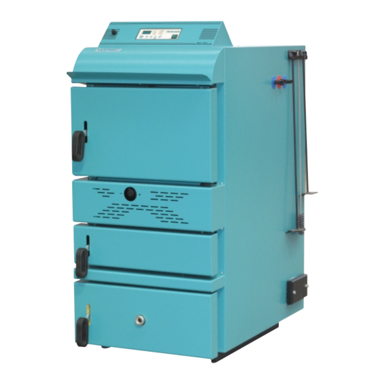
Bio-Tec
Advertisement
Table of Contents

Related Manuals for Centrometal Bio-Tec Series


Summary of Contents for Centrometal Bio-Tec Series
- Page 1 7% of the installation volume. Centrometal d.o.o. shall not be responsible for possible incorrect data caused by printing errors or error made in transcription and all figures and diagrams are for explanatory purposes only and relevant adjustment have to be made at the spot. In any case, it reserves the right to modify its products as deemed to be required and useful without any prior notification.
-
Page 2: Technical Data
Notes Technical data TECHNICAL DATA Bio-Tec 25 Bio-Tec 35 Bio-Tec 45 (kW) Nominal heat output (kW) Heat output range 12-25 Boiler class Required chimney underpressure (Pa) (lit.) Water amount in boiler (°C) Exhaust gas temperature at nominal heat output (°C) Exhaust gas temperature at minimum heat output Exhaust mass flow at nominal heat output (kg/s) - Page 3 Cleaning and mainternance of the boiler Dimensions of the boiler, basic parts DIMENSIONS AND BASIC PARTS OF THE BOILER Image 12. - Cleaning of Bio-Tec 25 Screw M8 (4 pcs.) VT VP Screw Fan flange Screw M8 (2 pcs.) Bio-Tec 35/45 Bio-Tec 25 Detail 1.
- Page 4 In general, characteristics Cleaning and mainternance of the boiler 1.0. IN GENERAL Image 11. - Cleaning of Bio-Tec 35/45 Steel boilers Bio-Tec, with an rated thermal output 25, 35 and 45 kW are constructed for wood firing and aimed for heating of small and middle sized Screw M8 premises.
-
Page 5: Delivery Package
Examples of inlet construction Wood gasification, delivery package, additional equipment Concerning the specific need of sanitary hot water, the Bio-Tec boiler can be connected to one of water heaters produced by our company. We suggest the Image 10. Examples of inlet construction combination with wall hanged SKB Digi or LKB Digi water heaters, as well as with standing TB water heaters and STEB solar water heaters, if the future connection to the solar system has been planned as also CAS-B or CAS-BS, combination of... - Page 6 Boiler / additional equipment positioning and assembly Cleaning and mainternance of the boiler 2.0. BOILER / ADDITIONAL EQUIPMENT POSITIONING AND ASSEMBLY The allocating of the boiler has to be carried out by the authorized person. We Cleaning of the flue gas chamber with flue gas tubes (Image 11.-DC): suggest the allocation on the solid concrete basis, which height is between - remove top back cover of the boiler casing (Image 11.-PD).
-
Page 7: Cleaning And Maintenance Of The Boiler
Cleaning and mainternance of the boiler Installation of moving parts 2.1. INSTALLATION OF MOVING PARTS 11.0. CLEANING AND MAINTENANCE OF THE BOILER Bio-Tec movable parts are delivered packed as a set within the top boiler chamber. After the boiler is placed in the boiler room, installation of movable parts is carried Protective gloves must be used (see Image 9). -
Page 8: Connection To The Chimney
Connection to the chimney, fresh air opening Boiler use 3.0. CONNECTION TO THE CHIMNEY - Close upper boiler doors. (see image 7) Properly calibrated and built chimney is the precondition for a safe operation of the - Turn the MAIN SWITCH on. (see Point 7.0) boiler and economic heating. -
Page 9: Boiler Use
Connection to the chimney, calibrating of the chimney Boiler use 10.0. BOILER USE Image 4. Incorrect connecting the boiler to the chimney Bio-Tec 35/45 Bio-Tec 25 Boiler must not be used in flammable and explosive environment. It must not be used by children or disabled persons (either physically or mentally), as well as by person without knowledge or experience, unless they are under control or trained by s person responsible for their safety. -
Page 10: Connection To The Central Heating System
Connection to the central heating system Connection to the open central heating system Fuel supply method 4.0. FRESH AIR OPENING Each boiler room must be equipped with an opening for supply of make up air Image 8. Fuel supply method which is dimensioned in accordance with boiler output (minimum opening area according to the below shown equation). - Page 11 Connection to the open central heating system Boiler start up Connection to the closed central heating system - After the regulation starts to display the lack of fuel , the fuel should be refilled (if it is necessary to continue the heating process)-BEFORE REFILLING, Scheme 1.
- Page 12 Connection to the closed central heating system Boiler start up - pieces of the lower refractory stone have to be situated into the deposits on the The boiler has to be connected to the one or more CAS water accumulators, depending of its power.
-
Page 13: Boiler Start Up
Electric connection, boiler start up Connection to the closed central heating system Scheme 4. - Electrical connection of a ordinal terminal on the boiler Scheme 2.1. - Closed central heating system with 3 or more water accumulators ordinal terminal ordinal terminal N N L 1 2 3 4 5 6 7 8 9 10 111213141516 1 - Boiler Bio-Tec... -
Page 14: Boiler Thermal Protection
Boiler thermal protection Boiler regulation 5.2.1. BOILER THERMAL PROTECTION By pressing two buttons simultaneously you can see different values: According to European EN standards, boiler thermal protection must be installed in Button ''P'' and buttons ''+'' or ''-'': display of measured values: closed heating system. -
Page 15: Boiler Regulation
Boiler regulation Thermal safety valve, steering of the boiler 7.0. BOILER REGULATION Scheme 3. - Thermal protection in an closed heating system 10 11 12 13 14 15 1 - Heat exchanger connection 2 - Connecting point for the thermal safety valve sensor 3 - Heat exchanger connection 4 - Thermal safety valve connection... - Page 16 Ignition phase, boiler operation phase Turning off digital regulation, thermal protection, safety protection 6.3. TURNING OFF DIGITAL REGULATION 6.1. IGNITION PHASE If it is necessary to turn off the digital regulation (control of heating pumps, sanitary After first boiler charging with fuel (see - Ignition phase and first fuel charging - page water and the pump between the boiler and water accumulation tanks), after the 21), it is necessary to push "START"...
Need help?
Do you have a question about the Bio-Tec Series and is the answer not in the manual?
Questions and answers