Advertisement
Quick Links
IMPORTANT SAFETY INSTRUCTIONS - SAVE THESE INSTRUCTIONS
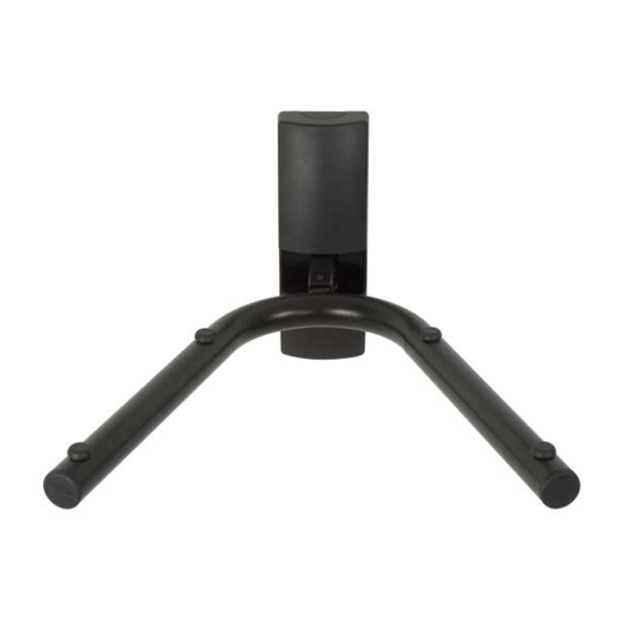
Thank you for choosing a Sanus Systems SANA1A. The SANA1A is designed to hold a single audio-visual component
weighing up to 45 lbs. [20.5 kg.], while concealing wire and cables.
The weight of your VCR, DVD player, cable box, satellite receiver, or stereo component must not exceed 45 lbs
(20.5 kg). The wall must be capable of supporting fi ve times the weight of the audio-visual component plus the
wall mount.
This mount is not intended for use on brick, concrete block, concrete, or steel wall studs. Typical wall anchors
do not have suffi cient holding power to support this mount. It is up to the installer to verify the safety of any
installation method or hardware that is not provided by or recommended by Sanus Systems.
Do not use this product for any purpose not explicitly specifi ed by Sanus Systems. Improper assembly may cause
property damage or personal injury. If you do not understand these directions, or have doubts about the safety
of the assembly, contact Customer Service or call a qualifi ed contractor. Sanus Systems is not responsible for
damage or injury caused by incorrect assembly or use.
This product contains small items that could be a choking hazard if swallowed. Keep these items away
from young children!
SANA1A
Sanus Systems 2221 Hwy 36 West, Saint Paul, MN 55113 USA
Customer Service: 1-800-359-5520 • 651-484-7988
info@sanus.com • www.sanus.com
©2008 Milestone AV Technologies
(6904-100080 <01>)
CAUTION
CAUTION
CAUTION
WARNING
Advertisement

Related Manuals for Sanus Systems SANA1A


Summary of Contents for Sanus Systems SANA1A
- Page 1 (6904-100080 <01>) IMPORTANT SAFETY INSTRUCTIONS - SAVE THESE INSTRUCTIONS Thank you for choosing a Sanus Systems SANA1A. The SANA1A is designed to hold a single audio-visual component weighing up to 45 lbs. [20.5 kg.], while concealing wire and cables. CAUTION The weight of your VCR, DVD player, cable box, satellite receiver, or stereo component must not exceed 45 lbs (20.5 kg).
- Page 2 1/8 in. 5/16 in. Hardware and procedures for multiple mounting configurations are included. When you see this symbol, choose the correct configuration to suit your needs. Not all hardware included will be used. Supplied Parts and Hardware Before starting assembly, verify all parts are included and undamaged. If any parts are missing or damaged, do not return the item to your dealer;...
- Page 3 1/8 in. [01] 63.5 mm (2.5 in.) 6904-100080 <01>...
- Page 4 CAUTION To prevent property damage and/or personal injury do not overtighten the lag bolts [05]. Tighten the lag bolts only until the wall plate [01] is pulled fi rmly against the wall. The drywall or other material must not exceed 15.8 mm (5/8 in.) in thickness.
- Page 5 Break out the appropriate knock out [K] on the cover [02] to route cables and wires out the top or bottom of the unit. [02] [01] [04] [03] [04] [03] 6904-100080 <01>...
- Page 6 [11] [06] [01] [03] [02] [06] [01] [03] [02] 6904-100080 <01>...
- Page 7 1/8 in. 38 mm (1.5 in.) CAUTION Do not overtighten the wood screws [09]. Tighten the screws only until the wall plate [07] is pulled fi rmly against the wall. The drywall or other material must not exceed 15.8 mm (5/8 in.) in thickness. [07] [09] [07]...
- Page 8 5/16 in. 38 mm (1.5 in.) [10] If mounting the cable cover wall plate [07] between studs, [07] use the 5/16 in. drill bit and anchors [10]. [09] [10] [07] 6904-100080 <01>...
- Page 9 NOTE Place all wires and cables between the right and left edge of the cable cover wall plate [07] prior to installing the cable cover [08]. [07] [08] Milestone AV Technologies and its affiliated corporations and subsidiaries (collectively, “Milestone”), intend to make this manual accurate and complete. However, Milestone makes no claim that the information contained herein covers all details, conditions, or variations.
Need help?
Do you have a question about the SANA1A and is the answer not in the manual?
Questions and answers