Advertisement
Quick Links
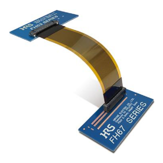
0.5mm Pitch, 3.57mm depth One Action Lock, Vertical connection FPC/FFC/Shield FFC connector
FH67 Series
■Features
1. Automatic one action lock design
One action locking by simply inserting FPC after
mounting contributes to enhanced workability. (Fig.1)
(Lock release by operating the lock lever when
removing.)
· Operation of the lock lever is not required at the time of
mating FPC. Can be inserted with one hand.
Contributes to reduced assembly time.
The lock lever will not be damaged by operation.
Mating failure due to FPC displacement does not occur
during lock lever operation.
2. Two-point contact prevents contact
failure by dust
· High contact reliability by independent spring two-point
contact design, preventing contact failure due to dust.
(Fig.2)
3. Supports FPC/FFC/Shield FFC
· FH67 allows you to choose from FPC/FFC/Shield FFC.
· Shielded FFC is acceptable for EMI prevention. (Fig.3)
4. High FPC retention force
· The circuit is automatically locked after FPC/FFC is
inserted by a one action. The notches on both sides of
FPC are held by the lock lever, generating a high FPC
retention force in spite of the small contact. (Fig.4)
5. Visual inspection on the mated status
of FPC/FFC is possible
· Insufficient insertion during assembly is prevented due
to lock lever protrusion after FPC/FFC insertion. (Fig.5)
6. Environmental
· Halogen free
*As defined by IEC 61249-2-21.
Br : 900ppm max, Cl : 900ppm max, Br+Cl : 1,500ppm
max
FPC/FFC can be checked from the top surface after mating.
○ : Mated condition
Viewing section
In cases where the application will demand a high level of reliability, such as automotive,
please contact a company representative for further information.
× : Insufficient insertion condition
Cannot see viewing section
Fig.5
One Action Lock (Dimension diagram : 30pos.)
Insert FPC/FFC
without opening the lock
lever before insertion!
5.2mm
Two-point contact design for dust prevention
Two-point independent spring contact
Supports FPC/FFC/Shield FFC
Shielded FFC is acceptable for EMI prevention
Shield FFC
Ground contact and FFC Ground plate contact at multiple points.
High FPC retention force
Robust lock firmly retains FPC/FFC.
Fig.1
3.57mm
Fig.2
Ground
contact
Fig.3
Fig.4
1
2019.10
Advertisement

Related Manuals for HRS FH67 Series


Summary of Contents for HRS FH67 Series
- Page 1 0.5mm Pitch, 3.57mm depth One Action Lock, Vertical connection FPC/FFC/Shield FFC connector FH67 Series One Action Lock (Dimension diagram : 30pos.) Insert FPC/FFC without opening the lock lever before insertion! 5.2mm Fig.1 3.57mm ■Features Two-point contact design for dust prevention 1.
-
Page 2: Product Specifications
FH67 Series●0.5mm Pitch, 3.57mm depth One Action Lock, Vertical connection FPC/FFC/Shield FFC connector ■ Product Specifications Rated Current 0.5A Operating temperature range -55 to +125°C (Note 1) Storage temperature range -10 to +60°C (Note 2) Rating Relative humidity 90% max. -
Page 3: Connector Dimensions
FH67 Series●0.5mm Pitch, 3.57mm depth One Action Lock, Vertical connection FPC/FFC/Shield FFC connector ■ Connector Dimensions (A) B±0.15 Ground contact No.2 D±0.1 2±0.1 D±0.1 Ground contact No.1 (0.1) Cavity No. (C) E±0.15 3.57±0.15 Polarity mark HRS mark Cavity No. Signal contact No.1 0.5±0.1... - Page 4 FH67 Series●0.5mm Pitch, 3.57mm depth One Action Lock, Vertical connection FPC/FFC/Shield FFC connector Recommended PCB Mounting Pattern (±0.02) (±0.02) 2× 0.6±0.02 0.02 H× 0.3±0.02 0.02 (0.25) n× 0.3±0.02 0.02 2× 0.6±0.02 0.02 (±0.02) Recommended Stencil Pattern (±0.02) (±0.02) 2× 0.6±0.01 0.02...
- Page 5 FH67 Series●0.5mm Pitch, 3.57mm depth One Action Lock, Vertical connection FPC/FFC/Shield FFC connector Recommended FPC/FFC Dimensions J±0.05 (K) 0.8±0.05 0.8±0.05 F±0.02 0.33±0.03 1.3±0.05 1.3±0.07 n× 0.4±0.03 R0.2 0.02 R0.2 R0.2 R0.1±0.1 R0.1±0.1 R0.2 R0.2 1.3±0.07 1.3±0.07 J±0.05 L±0.01 Recommended Shield FFC Dimensions J±0.05...
- Page 6 Tin plated 1 to 5µm ⑫ Surface treatment ―― ―― ⑬ ―― ―― ―― Shield tape Caution 1. This specification is recommendation for the construction of the FH67 series FPC/FFC/Shield FFC (t=0.33±0.03mm) 2. For details about the construction, please contact FPC/FFC/Shield FFC manufactures.
-
Page 7: Packaging Specifications
FH67 Series●0.5mm Pitch, 3.57mm depth One Action Lock, Vertical connection FPC/FFC/Shield FFC connector Packaging Specifications Embossed Carrier Tape Dimensions Tape width : 24mm or less Tape width : 32mm or less 8±0.1 4±0.1 (5.4) (2) (0.4) 8±0.1 4±0.1 (5.4) (2)... -
Page 8: Temperature Profile
FH67 Series●0.5mm Pitch, 3.57mm depth One Action Lock, Vertical connection FPC/FFC/Shield FFC connector Temperature Profile MAX 250°C Applicable Conditions Reflow method : IR/Hot air Reflow environment : Room air 220°C Solder : Paste type Sn/3.0Ag/0.5Cu (M705-GRN360-K2-V made by 180°C Senju Metal Industry Co.) - Page 9 FH67 Series●0.5mm Pitch, 3.57mm depth One Action Lock, Vertical connection FPC/FFC/Shield FFC connector [Operation Method] Care needs to be taken when handling this connector. In order to prevent the damage and contact failure etc. (incorrect mating, disconnection of FPC pattern) of connectors and FPC, please use after confirming the following contents.
- Page 10 FH67 Series●0.5mm Pitch, 3.57mm depth One Action Lock, Vertical connection FPC/FFC/Shield FFC connector [Operation Method] 2. How to insert FPC Insert FPC to the end correctly (Example 2) vertical to the board surface. [Caution] · Please confirm that the lock lever is closed when you insert FPC.
- Page 11 FH67 Series●0.5mm Pitch, 3.57mm depth One Action Lock, Vertical connection FPC/FFC/Shield FFC connector [Operation Method] (Example 7) (Example 8) (Example 9) FPC (diagonal) (diagonal) Lock lever (open) 3. Confirming the mated state of FPC When FPC is completely inserted, visually inspect the inserted status of FPC. (Example 10) (This connector uses the lock protrusion of the lock lever for positioning FPC.)
- Page 12 FH67 Series●0.5mm Pitch, 3.57mm depth One Action Lock, Vertical connection FPC/FFC/Shield FFC connector [Operation Method] 4. How to unlock the lock lever Push down the lock lever slowly, and release the lock. (Example 13) [Caution] · When releasing the lock operate the lock lever around the center. (Example 14) ·...
- Page 13 FH67 Series●0.5mm Pitch, 3.57mm depth One Action Lock, Vertical connection FPC/FFC/Shield FFC connector [Operation Method] (Example 16) (Example 17) Rotation axis Opening the lock lever Load is concentrated on the rotation at more than 45°. axis, and leads to breakage. (Example 18) (Example 19) Sharp-edged tools Applying excessive force to the lock lever.
- Page 14 FH67 Series●0.5mm Pitch, 3.57mm depth One Action Lock, Vertical connection FPC/FFC/Shield FFC connector [Operation Method] 5. How to remove the FPC After releasing the lock lever, remove the FPC vertically from the board side. (Example 20) When removing the FPC do not press the lock lever. (Example 21) The released lock lever is designed to close automatically at the time of FPC release.
- Page 15 FH67 Series●0.5mm Pitch, 3.57mm depth One Action Lock, Vertical connection FPC/FFC/Shield FFC connector [Operation method] [Cautions for PCB layout] Depending on the routing of the mating FPC, a load may be applied to the connector, which may cause failure. In order to prevent this, please consider the following concerning the mechanism design.
- Page 16 FH67 Series●0.5mm Pitch, 3.57mm depth One Action Lock, Vertical connection FPC/FFC/Shield FFC connector [Notes for mounting on the board/after mounting on the board] [Notes for board mounting] Please be careful of the following at the time of board mounting. [Caution] ·...
Need help?
Do you have a question about the FH67 Series and is the answer not in the manual?
Questions and answers