Advertisement
Quick Links
INSTRUCTION MANUAL FOR GT36A CONNECTOR
COUNT
DESCRIPTION OF REVISIONS
△
1
4
名 称
TITLE
INSTRUCTION MANUAL FOR GT36A CONNECTOR
TECHNICAL SPECIFICATION
FORM HC0011-9-1
DIS-T-00004327
DESIGNED
HK.WATANABE
HIROSE ELECTRIC CO.,LTD.
APPROVED
CHECKED
DESIGNED
WRITTEN
ETAD-T0401-01
CHECKED
DATE
MO.OKADA
20190311
KI.HIROKAWA
20171128
KI.HIROKAWA
20171128
KJ.OBINATA
20171128
KJ.OBINATA
20171128
1 / 7
△
1
Advertisement

Subscribe to Our Youtube Channel
Related Manuals for HRS GT36A


Summary of Contents for HRS GT36A
- Page 1 INSTRUCTION MANUAL FOR GT36A CONNECTOR COUNT DESCRIPTION OF REVISIONS DESIGNED CHECKED DATE △ DIS-T-00004327 HK.WATANABE MO.OKADA 20190311 名 称 TITLE HIROSE ELECTRIC CO.,LTD. APPROVED INSTRUCTION MANUAL FOR GT36A CONNECTOR KI.HIROKAWA 20171128 CHECKED KI.HIROKAWA 20171128 DESIGNED KJ.OBINATA 20171128 WRITTEN KJ.OBINATA 20171128 1 / 7 △...
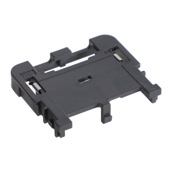
- Page 2 1. Names of Parts GT36 Female terminal GT36A Female housing GT36A Cover 2. Construction of Parts GT36 Female terminal Hirose part name Hirose part number Remarks GT36-2022SCF CL786-0002-0-00 For 2.5D GT36A-2022SCF CL786-0028-3-00 For 2.5D GT36-2428SCF CL786-0001-7-00 For 1.5D GT36-1.6-2.9SCF CL786-0003-2-00 For 1.5D...
- Page 3 3. Harness Work (1) Cutting cable Cut the cable according to the specified harness length. See below for the dimension L after wiring and the cable cutting length. Cable cutting length:L1- 9.6 L2+17.5 (2)Crimping terminals Refer to the terminal instruction manual for the terminal crimping procedures and crimping quality standards.
- Page 4 ①Insert a crimped GT36 female terminal along the terminal insertion hole into the housing to the end. After insertion, check if the terminal engagement is inserted into the housing engagement. Terminal engagement Housing engagement Terminal insertion hole * Coaxial cables and available cavities GT36A-4S-HU(*)×GT36A-4S-CV Cavities Coaxial cables 1.5D 1.5D 1.5D foaming (ETC)/2.5D 1.5D GT36A2-4S-HU(*)×GT36A2-4S-CV...
- Page 5 ② Insert the GT36A cover into the GT36A housing until it is engaged with the housing engagement and a click sound is heard. Housing engagement Engagement Cover ③Make sure that it is engaged with the engagement. △ 5 / 7 HIROSE ELECTRIC CO.,LTD.
- Page 6 4. Connector Engagement Procedures ①Adjust the direction of the notch of the board-side connector to that of the cable pullout side of the harness-side connector. Engagement direction Cable pullout side Notch ②Insert the connector until it is locked and a click sound is heard. The above figure shows the unfinished engaged condition.
- Page 7 5. Connector Disconnection Procedures ①Push the lock button until the connector is unlocked and pull it out. Lock Disconnection direction button Disconnection direction 6. Instructions ①Do not touch terminals unnecessarily. ②Do not put any object on a terminal. Do not drop terminals. Otherwise, terminals may be deformed or become dirty.
Need help?
Do you have a question about the GT36A and is the answer not in the manual?
Questions and answers