Advertisement
Quick Links
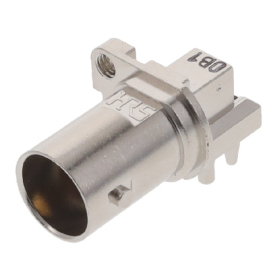
RF-21038
Mounting / Soldering procedure
for BNC 12G connectors
Products : BNC(75)-PLR-PC(D)-12G-3
CL302-0088-0-00
Hirose electric RF engineering team
RF-21038
Jan./
2022
The specification and contents are subject to change without notice. Please check the latest document.
2022.01
Advertisement

Subscribe to Our Youtube Channel
Related Manuals for HRS BNC75 Series


Summary of Contents for HRS BNC75 Series
- Page 1 RF-21038 Mounting / Soldering procedure for BNC 12G connectors Products : BNC(75)-PLR-PC(D)-12G-3 CL302-0088-0-00 Hirose electric RF engineering team RF-21038 Jan./ 2022 The specification and contents are subject to change without notice. Please check the latest document. 2022.01...
- Page 2 RF-21038 Mounting and soldering procedure Order 1. Positioning ⇒ 2. Outer contact soldering ⇒ 3. Center contact soldering ※Fluxing 1. Connector positioning for PCB Fluxing area: 4 Soldering areas of outer contacts and a soldering area of a center contact. A M2(mm) screw can be used for the temporally fixing.
- Page 3 RF-21038 Mounting and soldering procedure Order 1. Positioning ⇒ 2. Outer contact soldering ⇒ 3. Center contact soldering 2. Outer contact soldering 3. Center contact soldering Around Dia0.3mm solder suits for center contact soldering. - Wave soldering condition Preheat : max 100C / max 120sec Solder : max 245C/ max 5sec - Hand soldering condition Soldering at...
Need help?
Do you have a question about the BNC75 Series and is the answer not in the manual?
Questions and answers