LEYBOLD TRIVAC B Operating Instructions Manual
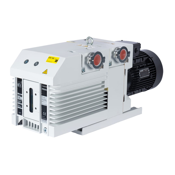
Rotary vane vacuum pump
Hide thumbs
Also See for TRIVAC B:
- Operating instructions manual (60 pages) ,
- Operating instructions manual (58 pages)

Related Manuals for LEYBOLD TRIVAC B


Summary of Contents for LEYBOLD TRIVAC B
- Page 1 LEYBOLD VACUUM Vacuum Solutions Application Support Service GA 01.203/10.02 TRIVAC ® Rotary Vane Vacuum Pump D 40 B, D 65 B Cat. No. 112 86/96 113 45/46/47/55/56/57 Operating Instructions...
-
Page 2: Table Of Contents
3.7 Removing and remounting the pump module . . 23 3.8 Leybold service ......25 3.9 Storing the pump ..... . . 25 3.10 Maintenance plan . - Page 3 We strongly recommend that you read Leybold-Service these Operating Instructions with care so as If a pump is returned to LEYBOLD, indicate whether the to ensure optimum operation of the pump pump is free of substances damaging to health or right from the start.
-
Page 4: Important Safety Considerations
• Make sure that the gas flow from the exhaust port is not blocked or restricted in any way. • The standard version of the TRIVAC B is not suited for operation in explosion hazard areas. Contact us before planning to use the pump under such circumstances. - Page 5 (> 25 mbar for water vapour). • Before pumping vapours, the TRIVAC B should have attained its operating temperature, and the gas ballast should be set to position I (position 0 = closed, position I = max. water vapour tolerance, 25 mbar).
-
Page 6: Description
1 Description TRIVAC B pumps are oil-sealed rotary vane pumps. The The drive motor of the TRIVAC B is directly flanged to the pump at the coupling housing. The pump and motor TRIVAC D 40 B and D 65 B are dual-stage pumps. The shafts are directly connected by a flexible coupling. -
Page 7: Function
In the pump chamber, the gas is passed front. on and compressed, after the inlet aperture is closed by To enable the TRIVAC B to be used at intake pressures the vane. as high as 1,000 mbar, a special lubricating system was... - Page 8 7 Gas inlet 4 Anti-suckback piston Fig. 4 Hydropneumatic anti-suckback valve The oil is separated from the gas in the TRIVAC B in two valve. Due to the pressure difference between the oil steps as described above. First, small droplets are...
-
Page 9: Supplied Equipment
177 01 (order from 177 02 LH Cologne, Germany) 20 l 177 03 The equipment supplied with the TRIVAC B pump includes: Oil HE-200 1 qt 98 198 006 Pump with motor, including initial filling of N 62 or HE-... -
Page 10: Technical Data
Description 1.6 Technical data 50 Hz operation, SI units D 40 B D 65 B · h Nominal pumping speed* Pumping speed* · h Ultimate partial pressure mbar < 1 · 10 < 1 · 10 without gas ballast* Ultimate total pressure mbar <... - Page 11 Description 1.6.1 Motor related data D 40 B D 65 B Cat.-No. Cat.-No. Motor-connection voltage, Motor Rated Speed Motor noise Order No. (mm) (kg) (mm) (kg) frequency power current level motor 112 86 3~, 230-240/380-420 V ±5 %, 50 Hz 1500 W 6,9/4 A 1400...
-
Page 12: Operation
(104 ϒF) and not drop below +12 ϒC (55 ϒF) (see Section 2.5.3). The TRIVAC B pump can be set up on a flat, horizontal surface. Rubber feet under the coupling housing ensure The max. amount of heat given off that the pump can not slip. -
Page 13: Connection To The System
System regulations and information sheets must be observed. Before connecting the TRIVAC B, remove the shipping The pumps may be operated with an inert gas ballast via seals from the connection flanges (7/2) and (7/3). a connection which is provided for this purpose. The... -
Page 14: Electrical Connection
Operation Delta connection Star connection Fig. 8 Connection diagram for TRIVAC B with 50 Hz 3-phase motor Caution After connecting the motor and after every 2.3 Electrical Connections time you alter the wiring, check the direction of rotation. To do so, briefly switch on the... -
Page 15: Start-Up
Operation 2.4 Start-up 2.4.1 Areas of Application Warning Before pumping oxygen (or other highly Caution Each time before starting up check the oil reactive gases) concentrations level. exceeding concentration atmosphere For pumps with 3-phase motors, check the direction of (> 21 % for oxygen) it will be necessary to rotation before starting the pump for the first time and use a special pump. -
Page 16: Operation
Operation 2.5 Operation In cyclic operation, the TRIVAC B should not be switched off during the intervals between the individual working phases (power consumption is minimal when the pump TRIVAC B pumps can pump condensable gases and is operating at ultimate pressure), but should continue to... -
Page 17: Switching Off/Shutdown
If the TRIVAC B is to be shutdown for an extended period can only be switched on again manually. after pumping aggressive or corrosive media or if the... -
Page 18: Maintenance
Caution If the TRIVAC B is used in ambient air which When wanting to check the oil, switch off the pump first is much contaminated, make sure that the... -
Page 19: Oil Change
Maintenance 3.2 Oil Change Warning Before pumping oxygen (or other highly reactive gases) concentrations exceeding concentration atmosphere (> 21 % for oxygen) it will be necessary to use a special pump. Such a pump will have to be modified and de-greased, and an inert special lubricant (like PFPE) must be used. -
Page 20: Removing And Fitting The Internal Demister
Maintenance Key to Fig. 10 1 Screw with small washer, spring, large washer and O-ring 2 Frame for demister 3 Demister 4 Oil case 5 Gasket 6 Fixing screws Fig. 10 Removal and fitting of the internal demister 3.4 Removing and Fitting Pull the oil case forward off the pump. -
Page 21: Disassembly And Reassembly Of The Electric Motor
Maintenance Key to Fig. 11 1 Gasket 2 Coupling with fan blades 3 Hex. socket screws 4 Intermediate flange 5 Hex. socket screws 6 Electric motor Fig. 11 Disassembly and reassembly of the electric motor 3.5 Disassembly and Unscrew the four non-recessed hex. socket screws (11/5). -
Page 22: Replacing The Shaft Seal
Maintenance Key to Fig. 12 1 Coupling element 2 Cylinder head screw 3 Spring washer 4 Coupling (one half) 5 Key 6 Compression ring 7 O-ring 8 Shaft seal 9 Screws 10 Centering disk 11 O-ring 12 Bushing Fig. 12 Exchanging the shaft seal 3.6 Replacing the Shaft Seal Unscrew screw (12/2) and pull off the spring washer (12/3). -
Page 23: Removing And Remounting The Pump Module
Maintenance If you do not have a shaft seal driver, place the shaft seal 3.7 Removing and on the centering disk and carefully Remounting the Pump force it in with light blows of the plastic hammer. Module The shaft seal must not be bent. Push the bushing (12/12) on to the shaft. - Page 24 Maintenance Key to Fig. 13 1 Hex. nuts 2 Pump module 4 Gasket 5 Coupling element 6 Tie rods Fig. 13 Removing and remounting the pump module 3.7.2 Remounting the Pump Module When installing a new pump module, it is also advisable to use a new gasket (13/3).
-
Page 25: Leybold Service
Maintenance 3.8 Leybold Service 3.9 Storing the Pump If a pump is returned to Leybold, indicate whether the Achtung pump free of substances damaging to health or whether Before putting a pump into operation once it is contaminated. If it is contaminated also indicate the more it should be stored in a dry place nature of the hazard. -
Page 26: Maintenance Plan
Maintenance 3.10 Maintenance Plan (Recommendation) Rotary vane pumps Measurement/test quantity Interval Remarks TRIVAC D 40 B Operating/auxiliary VE VP 6m a n-a Refer also to the Operating Instructions TRIVAC D 65 B materials – Chapter: individual components. Operate the pump for at least 0.8 Condensed water is thus removed from the oil. -
Page 27: Troubleshooting
• Checking of the individual components 6m = Six monthly maintenance • Exchange of all seals Annual maintenance • Functional check. n-a = Maintenance every n years. This check should be run by the Leybold service. GA 01.203/10.02 - 07/02... -
Page 28: Eec Declaration Of Conformity
EEC Declaration of Conformity We – LEYBOLD Vakuum GmbH – herewith declare that The products conform to the following directives: the products defined below meet the basic requirements • EC Directive on Machinery (98/37/EG) regarding safety and health of the relevant EC directives by design, type and versions which are brought into •... -
Page 29: Eec Manufacturer's Declaration
EEC Manufacturer’s Declaration in the sense of the Directive on Machinery 89/392/EWG, Annex IIb We – Leybold Vacuum GmbH – herewith declare that Applied harmonised standards: operation of the incomplete machine defined below, is • DIN EN 292 Part 1 11.91... - Page 30 GA 01.203/10.02 - 07/02...
- Page 31 GA 01.203/10.02 - 07/02...
- Page 32 Sales Net worldwide AMERICA EUROPE ASIA USA: Deutschland: Groß-Britannien/Irland: Volksrepublik China: Singapore: LEYBOLD VACUUM USA LEYBOLD VAKUUM LEYBOLD LTD. LEYBOLD (Tianjin) BALZERS and LEYBOLD 5700 Mellon Road GmbH Waterside Way, VACUUM EQUIPMENT Singapore Pte. Ltd. Export, PA 15632 Bonner Straße 498 Plough Lane MANUFACTURING Co.,...
Need help?
Do you have a question about the TRIVAC B and is the answer not in the manual?
Questions and answers