Table of Contents

Related Manuals for LEYBOLD MAG W 2010 CHT


Summary of Contents for LEYBOLD MAG W 2010 CHT
- Page 1 LEYBOLD VACUUM Vacuum Solutions Application Support Service GA 05.139/1.02 MAG W 2010 CHT Turbomolecular Pump with Magnetic Bearing MAG.DRIVE 2000 Electronic Frequency Converter Software version 1.4.xx Cat. Nos. 121 31 121 44 Operating Instructions...
-
Page 2: Table Of Contents
Removing the pump from the system ..46 and the converter. If they have different numbers, the Service at Leybold’s ....48 version delivered with the pump describes the pump correctly and the version delivered with the converter Troubleshooting . -
Page 3: Description
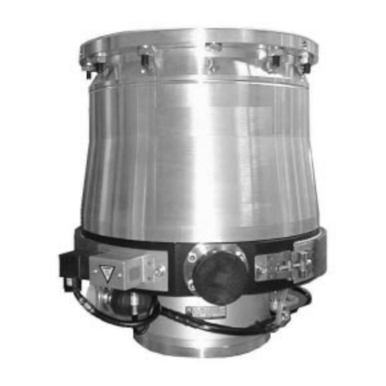
Description 1 Description 1.1 System overview The Leybold MAG pumping system consists of: • The MAG W 2010 CHT turbopump The MAG are turbomolecular pumps utilizing magne- tic bearings.They are designed to evacuate vacuum chambers down to pressure values in the high-vacu- um range and to pump high gas throughputs. -
Page 4: Compatibility With Pumped Media
(at pressures below about 100 mbar). A hazardous condition will be created The MAG W 2010 CHT is specifically designed for the if flammable mixtures enter the hot pump at pressures needs of the semiconductor industry. -
Page 5: Function And Design Of The Mag.drive
Description Motor and control Housing A DC motor without commutator is used to power the The converter is supplied with a closed housing. It can rotor. be installed in a 19” cabinet; see Section 2.8. Drive voltage for the motor and the operating voltage for the magnetic bearing are supplied by the MAG.DRIVE Front panel frequency converter. -
Page 6: Standard Specification
Description 1.5 Standard specification 1.6 Technical data MAG W 2010 CHT The turbomolecular pumps are shipped complete, Pumping speed for N measured sealed in a PE bag containing a desiccant. with splinter guard (PNEUROP) 1650 l·s Gas flow (continuous operation... - Page 7 Description Each Fuse 4 A MAG.DRIVE 2000 Each Fuse 4 A Prog Enter Start Stop MAG.DRIVE 2000 with plug-in control Fig. 3 Front panel X14 Connection control plug X19 Mains connection X20 Connection magnetic bearing X21 Connection pump motor and Fig.4 Rear panel with connections GA 05.139/1.02 - 06/99...
-
Page 8: Ordering Information
Description Technical data 1.7 Ordering data (continued) MAG.DRIVE Order No. MAG W 2010 CHT 121 31 Voltage range 200 - 240 V +10% -15% Line supply frequency 50 / 60 Hz Load Seal Kit DN 250 standard 200 91 641 Stand-by approx. - Page 9 Description 0° 40° 0° 90° 270° BEARING connection DRIVE/TMS connection DRIVE connection connection 180° BEARING connection 225° 180° Connecting cables converter — pump Length Cable Cable outlet Cable outlet Order No. Converter Pump ————————————————————————————————————————— 1.5 m BEARING bended 40° bended 140° 121 29 1.5 m DRIVE/TMS...
- Page 10 Description max. 115 straight plugs bended plugs Ø 3.3 Each Fuse 4 A 122.4 t u s S t a 19“ installation frame I V E 4 x M3 screws Fig. 6 Dimensional drawing and standard fixing of the MAG.DRIVE; dimensions in mm GA 05.139/1.02 - 06/99...
- Page 11 Description ø335 ø 310 ø284 ø261 DN 250 ISO F ø355 ø199 Fig. 7 MAG W 2010 CHT, Dimensions in mm GA 05.139/1.02 - 06/99...
- Page 12 480 Hz Purge gas flow 36 sccm Nitrogen with splinter guard Forepump D 65 B + WS 251 Pipe 1 m DN 40 according to PNEUROP Fig. 9 MAG W 2010 CHT: operation diagram for nitrogen GA 05.139/1.02 - 06/99...
-
Page 13: Installation
If this unit is dama- Only suitably qualified personnel are per- ged contact your carrier and inform LEYBOLD if neces- mitted to work on the pump or converter. sary. For storage of the product, use the packaging pro- Personnel must be completely knowledgea- vided. -
Page 14: Operating Environment
Installation 1 Aluminum cover 2 Screws Fig. 10 Removing the transport seal 2.4 Connecting the MAG to 2.3 Operating environment the vacuum chamber When using the MAG inside a magnetic field, the magnetic induction at the pump housing must not ex- The MAG is shipped in a sealed PE bag with desiccant. - Page 15 60,000 Nm will have to be absorbed by the system. To accomplish The standard fixing for the converter is shown in Fig. 6. this, use all 12 bolts provided by Leybold for fastening the high-vacuum flange; see also Fig. 15.
- Page 16 Installation M = 60,000 Nm M = 60,000 Nm Correct Wrong Fig. 13 Vacuum chamber fixed to the floor 125 ° Boreholes M8, 15 mm deep Fig. 14 Fixing the pump at the bottom GA 05.139/1.02 - 06/99...
- Page 17 Installation Bolts: M10 x 35 / M10 x 40 Quality 12.9 according to DIN 898: 0,2% yield strength > 1080 N/mm Bolt torque: 40 Nm Outer ring (stainless steel) Sealing (FPM) l > 15 mm in aluminium Centering ring (stainless steel) l >...
- Page 18 Installation Key to Fig. 16 Turbomolecular pump Forevacuum gauge point Backing pump Anti-vibration bellows Forevacuum valve High vacuum valve Purge gas connection Valve in the roughing line Electronic frequency converter — — — — roughing line; recommended if shorter cycle times are to be achieved —...
-
Page 19: Connecting The Backing Pump
Installation M < 150 Nm < 150 Nm Fig. 17 Maximum torques for the forevacuum connection 2.5 Connecting the backing In case of an oil-sealed backing pump the foreline isola- tion valve protects the MAG from backstreaming oil pump vapor during standstill. Connect the forevacuum flange of the MAG to the A two stage rotary vane pump or dry-compression backing pump. -
Page 20: Connecting The Cooling Water
Installation Operation window °C bar over Temperature Pressure atmosphere Fig. 18 Recommended cooling water flow 2.6 Connecting the cooling Connect the cooling water to the connectors; see Fig. water Caution Make sure that you do not mix up the inlet Cooling water specifications and the outlet connection. - Page 21 Installation Cooling water out Cooling water in Cooling water in WRONG Cooling water out MAG cooling circuit Cooling valve Fig. 19 Connecting the cooling water GA 05.139/1.02 - 06/99...
-
Page 22: Connecting The Purge Gas
Installation 2.7 Connecting the purge The MAG is equipped with a purge gas connector. To ensure protection of the pump a constant purge gas throughput of 30 to 40 sccm is required. You may use a flow controller to ensure the flow. Inadequate purge gas flow voids the warranty. - Page 23 Installation Male connector: Tube OD 1/4“ - ISO male pipe size: 1/4“ Port connector: Tube to VCR VCR Nut 1/4“ Fig. 20 Purge gas connection with connection kit GA 05.139/1.02 - 06/99...
-
Page 24: Installing The Mag.drive
Death or severe injury can occur if you come into contact with these hazar- The MAG W 2010 CHT can only be opera- dous voltages. Before opening the conver- ted with the MAG.DRIVE 2000 converter ter, isolate the converter from the line supp- and not with the MAG.DRIVE L or L2. -
Page 25: Power Supply Connection X10
Installation Fig. 21 Mounting the safety sleeves; rear side of the converter shown. Mount the safety sleeve onto the pump’s TMS connection too. 2.8.1 Power supply connection X19 The converter is ready to be connected to line supply voltages between 200-240 V 50/60 Hz. The connection is established using the power cable supplied, which is inserted at connector X19 at the rear of the converter. -
Page 26: Pump Connection
Installation BEARING DRIVE MAINS Control plug Fig. 23 Block wiring diagram 2.8.2 Pump connection Warning To avoid contact with hazardous voltages in case of malfunction the pump must be connected to PE, see Fig. 24. Connect the converter (X20) to the magnetic bearing connection of the pump (X23) using the BEARING cable. -
Page 27: Control Plug X14
Installation EMERGENCY OFF X14.47 EMERGENCY OFF active EMERGENCY OFF X14.48 Borehole M8, 15 mm deep for PE connection Fig. 24 PE connection for the pump Fig. 25 Control plug X14: Emergency off 2.8.3 Control plug X14 Description of the Emergency Off connection Pins 47 and 48 of control plug X14 make it possible to Emergency off disable the output stage of the frequency converter via... - Page 28 We recommend using only the default set- ————— tings for the option relays 7, 8, and 9. 1) not active at MAG W 2010 CHT GA 05.139/1.02 - 06/99...
- Page 29 Installation Relay 1 Failure No failure X14.18 X14. Start command applied Relay 2 Normal Operation & X14.19 Actual frequency X14.2 Normal operation X14.35 Relay 3 Warning Warning X14.20 X14.3 X14.36 Relay 4 Acceleration Acceleration X14.21 X14.4 X14.37 Relay 5 Deceleration Deceleration X14.22 X14.5...
- Page 30 Scale Analog output Rotor displacement X14.50 PVW13peak PVW24peak X14.32/33 Analog ground PZ12peak Current limiting +15 V X14.24/28 80 mA ————— 1) not active at MAG W 2010 CHT Fig. 28 Function diagram outputs, Part 2 GA 05.139/1.02 - 06/99...
-
Page 31: Interface Connector
A 9-pin sub-D socket is provided at the front panel. The lution. connector X7 is assigned the serial interface RS 232. It is only to be used by the Leybold Service. Input signal: 0...10V A supplementary function can be set for analog input 2 via the operator control menu;... -
Page 32: Operation
Operation 3 Operation 3.1 General operation rules Warning Monitor the purge gas continuously. The magnetic bearing in the MAG are immune to wear. Insufficient purge gas flow can result in: In addition to the magnetic bearings, the MAG is equip- - Process gases entering the motor and ped with touch-down bearings which protect the rotor bearing area of the MAG... - Page 33 Operation Forevacuum pressure/mbar Time/s Fig. 30 Curve for safe venting of the MAG; pressure rise as a function of venting time GA 05.139/1.02 - 06/99...
-
Page 34: Operation With The Start And Stop Keys
Operation 3.2 Operation with the Significance of the lamps START and STOP keys (green) Is lit if communication has been established via the Switching on interface. • Switch on the MAG.DRIVE. STATUS (green/red) The MAIN LED lights green. Red, steady light = Failure If the pump has the optional TMS (including e.g. -
Page 35: Remote Control
Operation +15 V ~ 3 kOhm X14.48 Shutdown X14.47 X14.11 Operating mode: REMOTE 0 V = 0 Programming only via 15 V = 1 X14.12 serial interface START Start delay time X14.30/31 START interface START & pump START key pad STOP key pad ≥1... -
Page 36: Plug-In Control
Plug-in control 4 Plug-in control 4.1 Operation with plug-in Switching off control The MAG.DRIVE controls the venting automatically pro- vided purge gas is connected to the MAG and the MAG.DRIVE is programmed correspondingly („Vent Observe the general operation rules given on“). - Page 37 Plug-in control Function • Returns to the operating display from the storage procedure without storage. • Returns to the operating display from any point of the basic menu. Acceleration • No function 17.5A 254Hz HOK Prog • Selects the programming menu from the operating display. •...
-
Page 38: Operating Statuses
Plug-in control 4.2 Operating statuses Overload The speed is continuously monitored and controlled. If Switch-On Guard the speed, even at maximum current, cannot be held at the setpoint, as a result of external influences, e.g. The converter goes into the “Switch On Guard” operating excessive gas intake, the speed reduces until the con- status after the power is switched on and after initializa- verter goes into the „Overload“... - Page 39 Plug-in control Mains switched on Initialization Switch On Guard After a failure, quit a second time Ready START command STOP command Start Delay Mains ok Mains failure Acceleration Frequency > P 25 x P24 Mains failure Mains Down Normal Operation Frequency <...
-
Page 40: Operating Menu
Plug-in control 4.3 Operating menu 4.3.1 Basic menu Menu item Description Adjustable value / option cess min. max. stan- Unit value value dard Ready Operating display Ready 0.0 A 0 Hz Enter Freq. Setpoint Sets the speed for operation Freq. Setpoint !! Every change is directly written 480 Hz into the pump’s data storage... -
Page 41: Settings Converter
Plug-in control 4.3.2 Settings converter Set Converter Menu item Description Adjustable value / option cess Enter min. max. stan- Unit Option Relay 1 value value dard Bearing Temp. Motor Current Option Relay 1 Relay with change-over Threshold bearing Frequency °C (Relay 6) contact;... -
Page 42: Settings Pump
Set TMS °C TMS Setpoint Setpoint Temperature- Management-System Enter TMS Setpoint 60 °C Enter 4.3.5 Settings purge / vent (Not active at MAG W 2010 CHT) Menu item Description Adjustable value / option Set Purge/Vent cess min. max. stan- Unit... -
Page 43: Total View Of The Menu
Basic menu Programming menu Not active at MAG W 2010 CHT Main menus Ready Set Converter Set Pump Set TMS Set Purge/Vent 0.0 A 0 Hz Enter Enter Enter Enter Enter Purge/Vent Freq. Setpoint Option Relay 1 Normal Operation TMS Setpoint 60 °C... -
Page 44: Temperature Management System
X14, Relay outputs) Principally the factory presetting will be used. The setting is saved in the pump’s memory chip. Before changing any setpoint value request Leybold! Warning message (Temp > T +5K) For the setting refer to 4.3.4 Operating menu, Settings TMS. - Page 45 Plug-in control T + 15 K T + 5 K T + 2 K Sollwert TMS Setpoint temp. T T - 2 K T - 5 K TMS Code TMS Code Heizung EIN Heater ON Kühlung EIN Cooling ON TMS OK TMS ok Warnung TMS Warning Temp.
-
Page 46: Maintenance
Therefore the converter must be cleaned after 5 dous gases, ensure that proper safety pre- years. cautions are taken before opening the inta- Only the Leybold service can change the rotor and clean ke or exhaust connections. the converter. Use gloves or protective clothing to avoid skin contact with toxic or highly corrosive substances. - Page 47 Maintenance ring nut (2x) aluminum cover plastic adhesive film washer (6x) screw (6x) nut (4x) dry cartridge plastic adhesive film plastic cap Fig. 37 Sealing the MAG tightly Seal the high-vacuum connection flange with the cover and the screws. Pack the pump so that it may not be damaged during transportation.
-
Page 48: Service At Leybold's
Maintenance 5.2 Service at Leybold’s If you send a pump to Leybold indicate whether the pump is free of substances damaging to health or whether it is contaminated. If it is contaminated also indi- cate the nature of hazard. To do so, you must use a pre- printed form which we shall send to you upon request. - Page 49 Maintenance bolts collar flange retaining ring blank flange Centering ring with O-ring desiccant desiccant nuts centering ring with O-ring blank flange sealing disc clamping ring screwed sealing plug for purge gas connector polyethylene bag with cable tie Fig. 38 Sealing the MAG tightly with the metal seal kit GA 05.139/1.02 - 06/99...
-
Page 50: Troubleshooting
Section 4.3.1. Temperature sensor inside Reduce gas load. If the warning persists the motor reads a higher contact Leybold service. temperature value than the warning threshold (100 °C). Drive failure or internal converter failure. Contact Leybold service. - Page 51 The pump drive is blocked. PK Communication BEARING cable damaged. Check BEARING connector and cable for damages or bent pins. Contact Leybold ser- Converter does not commu- vice if the cable is damaged. nicate with the memory chip inside of the pump.
-
Page 52: Failure Messages
Replace the cable if it is damaged or in case the measurement of the resistance shows abnormal values (> 3.4 kΩ) now. Converter failure. Contact Leybold service. Cooling Temp. Cooling water flow too low or cooling Apply cooling water according to specifications. - Page 53 0 and 5 seal on power up. Check BEARING connector and cable for bent Hz. The code designates the BEARING cable or connector dama- pins. Contact Leybold service if the cable is dama- affected axis. ged. ged. GA 05.139/1.02 - 06/99...
- Page 54 Reduce backing pressure. The frequency has not rea- Rotor blocked. Check if the rotor rotates freely. Contact ched 40 Hz 2 minutes after Leybold service if the rotor is damaged or the start command was blocked. applied. Accel. Time Backing pressure too high during start-up.
- Page 55 Measures Bearing Temp. SC Temperature sensor Pt 100 short-circuited. Repeat step 1 of „failure Bearing Temp.“. Contact Leybold service if the resistance of The magnetic bearing tem- the sensor is less than 100 Ω. perature sensor reads a tem- perature lower than 1 °C.
- Page 56 Check the line voltage (200-240 V +10% / -15%). The converter measures a Heating element defective. Repeat step 2of failure TMS 1. In case the measu- red value is less than 60 Ω contact Leybold servi- heating current of more than 4 A. Converter failure.
-
Page 57: Malfunctions
Display malfunction, confu- Converter failure. Switch the converter off and on again. If the sing messages. No reaction converter still malfunctions contact Leybold when pressing keys. service. Vacuum chamber pressure Purge gas and venting valve open or mal-... -
Page 58: Certifications
Certifications EEC Manufacturer’s Declaration in the sense of EEC Directive on Machinery 89/392/EWG, Annex IIb We - LEYBOLD Vacuum GmbH - herewith declare that Applied harmonized standards: operation of the incomplete machine defined below, is • EN 292 Part 1 & 2 Nov. - Page 59 Certifications EC declaration of manufacture in accordance with Art. 4 paragraph 2 of EC directive 89/392/EEC Document No.: MSR 0898 / MAG.DRIVE 2000 Manufacturer: REFU elektronik GmbH Product Identification: MAG.DRIVE 2000 Catalog No.: 121 35, 121 36, 121 37, 121 44 The product indicated solely for fitting in another machine.
- Page 60 Certifications EC declaration of conformity Document No.: NSR 0898 / MAG.DRIVE 2000 Manufacturer: REFU elektronik GmbH Product Identification: MAG.DRIVE 2000 Catalog No.: 121 35, 121 36, 121 37, 121 44 Herewith, we declare that this product, as a result of ist design and type of construction, and the version marketed by us, correspond to the basic health and safety regulations specified in the EEC Directives.
- Page 61 Certifications Factory certificate Document No.: EMV 0898 / MAG.DRIVE 2000 Manufacturer: REFU elektronik GmbH Product Identification: MAG.DRIVE 2000 Catalog No.: 121 35, 121 36, 121 37, 121 44 The named product, when put to ist intended use, satisfies the requirements of Directive 89/336/EEC concerning electromagnetic compatibility.
- Page 62 Certifications The system MAG 2000 The tested system includes the following components: • turbomolecular pump Turbomolecular pump MAG (W) 1600/2000, Cat. Nos. 121 31, 121 32 • connecting cables 894 14, 894 15, 894 16, 894 17, • frequency converter 894 28, 894 29, 894 30, 894 31 has been tested by the TÜV Rheinland of North America Frequency converter MAG.DRIVE 2000,...
- Page 63 Notes GA 05.139/1.02 - 06/99...
-
Page 64: Forms
Declaration of Contamination of Vacuum Equipment and Components The repair and/or service of vacuum equipment and components will only be carried out if a correctly completed declaration has been submitted. Non-completion will result in delay. The manufacturer could refuse to accept any equipment without a declara- tion. - Page 65 Process Gas: Was the turbopump replaced? Yes; If yes, replacement pump P/N: replacement pump S/N: Date Installed: Date Removed: Date Received: Date Examined: Examined by: Received Condition: Findings: Cause of Failure: Recommendations: Remarks/Questions: LEYBOLD VACUUM LEYBOLD AG GA 05.139/1.02 - 06/99...
- Page 66 3 Beta site units (July 1998) GA 05.136/2.02 MAG W 2010 C MAG.DRIVE 2000 (October 1998) GA 05.139/1.02 MAG W 2010 CHT MAG.DRIVE 2000 (June 1999) including NRTL & SEMI S2 certifications LEYBOLD VAKUUM GmbH Bonner Strasse 498 (Bayenthal) D-50968 Cologne Tel.: + 49 (221) 347-0...
Need help?
Do you have a question about the MAG W 2010 CHT and is the answer not in the manual?
Questions and answers