Table of Contents
Advertisement
Quick Links
One Technology Way P.O. Box 9106 Norwood, MA 02062-9106, U.S.A. Tel: 781.329.4700 Fax: 781.461.3113 www.analog.com
Evaluating the
ADP5350
FEATURES
Input voltage: 4.0 V to 5.38 V
Full featured evaluation board for the
Evaluation software and installation CD included
Simple device measurements and demonstrable with
A voltage supply
A battery or battery simulator
Load resistors or an electrical load
EQUIPMENT NEEDED
2
USB to I
C dongle
USB-SDP-CABLEZ
evaluation kit and must be ordered separately)
SOFTWARE NEEDED
ADP5350CP-EVALZ
graphic user interface (GUI) software
PLEASE SEE THE LAST PAGE FOR AN IMPORTANT
WARNING AND LEGAL TERMS AND CONDITIONS.
Battery Management PMIC with Inductive Boost LED and
Three LDO Regulators
ADP5350
(not included in the
ADP5350CP-EVALZ
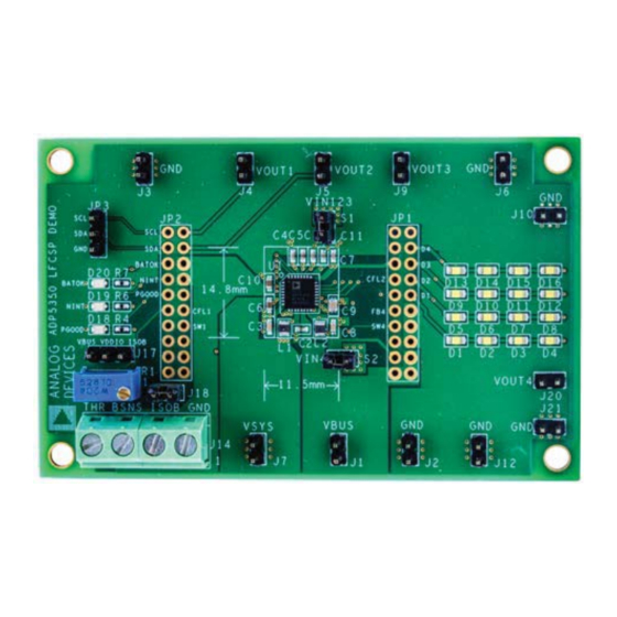
Figure 1.
Rev. 0 | Page 1 of 15
ADP5350CP-EVALZ User Guide
GENERAL DESCRIPTION
This user guide describes the hardware and software for the
evaluation of the
ADP5350CP-EVALZ
includes detailed schematics and printed circuit board (PCB)
layouts.
The
ADP5350
combines one high performance buck regulator
for single Li-ion/Li-ion polymer battery charging, a fuel gauge,
a highly programmable boost regulator for LED backlight
illumination, one ultralow quiescent current low dropout
(LDO) regulator, and two general-purpose LDO regulators.
The
ADP5350CP-EVALZ
external USB dongle connection and the GUI software allows
the user to evaluate the comprehensive functionalities provided
2
by the I
C interface.
The
ADP5350
operates over the −40°C to +125°C junction
temperature range and is available in a 32-lead, 5 mm × 5 mm
LFCSP package.
Full details on the device are provided in the
sheet, available from Analog Devices, Inc., which must be
consulted in conjunction with this evaluation board user guide.
EVALUATION BOARD
UG-1104
evaluation board, and
evaluation board supports an
ADP5350
data
Advertisement
Table of Contents

Subscribe to Our Youtube Channel
Related Manuals for Analog Devices ADP5350CP-EVALZ


Summary of Contents for Analog Devices ADP5350CP-EVALZ
-
Page 1: Features
32-lead, 5 mm × 5 mm LFCSP package. Full details on the device are provided in the ADP5350 data sheet, available from Analog Devices, Inc., which must be consulted in conjunction with this evaluation board user guide. ADP5350CP-EVALZ EVALUATION BOARD Figure 1. -
Page 2: Table Of Contents
Fuel Gauge Function Evaluation ..........10 Installing the ADP5350 GUI Software ........3 LED and LDO Function Evaluation ........10 Installing the Analog Devices SDP Drivers ......4 Evaluation Board Schematics and Artwork ........ 12 Using ADP5350 GUI Software ............5 Ordering Information .............. -
Page 3: Installing The Software
ADP5350CP-EVALZ User Guide UG-1104 INSTALLING THE SOFTWARE ADP5350CP-EVALZ GUI software allows evaluation of all Click Next to install the program (see Figure 4). functions and features of the program registers. Before starting the software installation, ensure that the ADP5350CP-EVALZ evaluation board is not connected to the USB port of the PC. -
Page 4: Installing The Analog Devices Sdp Drivers
UG-1104 ADP5350CP-EVALZ User Guide INSTALLING THE ANALOG DEVICES SDP DRIVERS Click Finish to complete the driver installation (see Figure 8). To install the Analog Devices system demonstration platform (SDP) drivers, complete the following steps: After installing ADP5350CP-EVALZ GUI software, the installation of the SDP drivers begins. -
Page 5: Using Adp5350 Gui Software
After the input power supply is connected and is between 4.0 V and 5.38 V, the ADP5350 begins charging. If the resistance in Ensure that the Analog Devices USB to I C dongle, the THR input corresponds to a battery temperature of between USB-SDP-CABLEZ, is plugged into the USB port of 0°C and 60°C (or to the temperature programmed from I... -
Page 6: Battery Soc Settings
UG-1104 ADP5350CP-EVALZ User Guide BATTERY SOC SETTINGS LED LIGHTING, BOOST, AND LDO SETTINGS Program the battery state of charge (SOC) settings by adjusting In the LED&LDO Control tab, program the boost mode the voltage and internal battery resistance, which varies with selection, LED lighting functionalities, fade in/out settings, temperature, in the Battery SoC tab (see Figure 11). -
Page 7: Direct Register Write And Read
ADP5350CP-EVALZ User Guide UG-1104 DIRECT REGISTER WRITE AND READ Register 0x00 and Register 0x01, are read only registers and cannot be overwritten. It is possible to read and write the content of each register using the Register R&W tab as shown in the GUI (see Figure 13). -
Page 8: Gui Troubleshooting
UG-1104 ADP5350CP-EVALZ User Guide GUI TROUBLESHOOTING window, next to the STOP button, this may mean the I C bus is not detecting the ADP5350. Check that the cable is securely If the GUI is not responding and the Hardware Select window... -
Page 9: Using The Evaluation Board
Use a dc power supply to connect VBUS and GND on the Input Jumpers ADP5350CP-EVALZ. Set the VBUS supply to 5. 0 V, and Because VIN123 and VIN4 must be connected to VSYS, the turn the power on. If evaluation of the charge function is input jumpers, S1 and S2, are shunted by default. -
Page 10: Evaluation Board Measurements
UG-1104 ADP5350CP-EVALZ User Guide EVALUATION BOARD MEASUREMENTS CHARGE FUNCTION EVALUATION The die temperature, T , exceeds the isothermal charging temperature, T (typically 115°C). Input Current Limit The available current from the dc-to-dc converter output The input current-limit function of the... - Page 11 ADP5350CP-EVALZ User Guide UG-1104 LED Indication LDO Measurement To set LED3 as an individual LED with the blink indication The LDO1 by default is always powered on. The output voltage feature, follow these steps: of all three LDO regulators can be programmed in the LED&LDO Control tab.
-
Page 12: Evaluation Board Schematics And Artwork
UG-1104 ADP5350CP-EVALZ User Guide EVALUATION BOARD SCHEMATICS AND ARTWORK Figure 16. Evaluation Board Schematic of the ADP5350CP-EVALZ Evaluation Board Figure 17. Top Layer, Recommended Layout for the ADP5350CP-EVALZ Evaluation Board Rev. 0 | Page 12 of 15... - Page 13 ADP5350CP-EVALZ User Guide UG-1104 Figure 18. Second Layer, Recommended Layout for the ADP5350CP-EVALZ Evaluation Board Figure 19. Third Layer, Recommended Layout for the ADP5350CP-EVALZ Evaluation Board Rev. 0 | Page 13 of 15...
- Page 14 UG-1104 ADP5350CP-EVALZ User Guide Figure 20. Bottom Layer, Recommended Layout for the ADP5350CP-EVALZ Evaluation Board Rev. 0 | Page 14 of 15...
-
Page 15: Ordering Information
By using the evaluation board discussed herein (together with any tools, components documentation or support materials, the “Evaluation Board”), you are agreeing to be bound by the terms and conditions set forth below (“Agreement”) unless you have purchased the Evaluation Board, in which case the Analog Devices Standard Terms and Conditions of Sale shall govern. Do not use the Evaluation Board until you have read and agreed to the Agreement.
Need help?
Do you have a question about the ADP5350CP-EVALZ and is the answer not in the manual?
Questions and answers