Table of Contents
Advertisement
Quick Links
Advertisement
Table of Contents

Subscribe to Our Youtube Channel
Related Manuals for Brymen BM859s


Summary of Contents for Brymen BM859s
- Page 1 USER'S MANUAL BM857s BM859s...
-
Page 2: Terms In This Manual
1) SAFETY This manual contains information and warnings that must be followed for operating the instrument safely and maintaining the instrument in a safe operating condition. If the instrument is used in a manner not specified by the manufacturer, the protection provided by the instrument may be impaired. -
Page 3: International Electrical Symbols
WARNING To reduce the risk of fire or electric shock, do not expose this product to rain or moisture. To avoid electrical shock hazard, observe the proper safety precautions when working with voltages above 60 VDC or 30 VAC rms. These voltage levels pose a potential shock hazard to the user. -
Page 4: Product Description
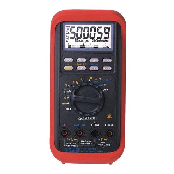
3) PRODUCT DESCRIPTION Panel Illustration 1) 5-4/5 digits 500000 counts LCD display 2) Push-buttons for special functions & features 3) Selector to turn the Power On or Off and Select a function 4) Input Jack for 10A (+) (20A for 30sec) current, and for T2 (-) function 5) Input Jack (+) for all functions EXCEPT current... - Page 5 sinusoidal waveform, this technique is fast, accurate, and cost effective. In measuring non-sinusoidal waveforms, however, significant errors can be introduced because of different scaling factors relating average to RMS values. AC True RMS AC True RMS, normally refers as True RMS, identifies a DMM function that is AC coupled, and responds accurately only to the effective RMS AC component value regardless of the waveforms.
-
Page 6: Operation Caution
CMRR (Common Mode Rejection Ratio) Common mode voltage is voltage present on both the COM and VOLTAGE input terminals of a DMM, with respect to ground. CMRR is the DMM's ability to reject common mode voltage effect that can cause digit rolling or offset in voltage measurements. - Page 7 Note: Line Level Frequency measuring function input sensitivity varies automatically with voltage (or current) function range selected. The lower the measuring range the higher the sensitivity. That is, mV function has the highest and the 1000V range has the lowest as in voltage function ranges. It is recommended to first measure the signal voltage (or current) level then activate the Hz function in that voltage (or current) range to automatically get the most appropriate trigger level.
- Page 8 Hz Logic Level Frequency and % Duty Cycle functions Press SELECT button momentarily to toggle between Hz and % (duty cycle) readings. The new setting will be saved automatically to the non-volatile memory as power up default. Press 500000 button momentarily to toggle between 5 full digits and 6 full digits Hz readings.
- Page 9 Resistance, Continuity functions Press SELECT button momentarily to toggle between and Continuity functions. The new setting will be saved automatically to the non-volatile memory as power up default. Continuity function is convenient for checking wiring connections and operation of switches.
- Page 10 CAUTION Using resistance or continuity function in a live circuit will produce false results and may damage the meter. In many cases the suspected component must be disconnected from the circuit to obtain an accurate reading. Capacitance, Diode test function Press SELECT button momentarily to toggle between Capacitance and Diode test functions.
- Page 11 A, mA, A, and %4-20mA Current functions Insert the red test lead into the correct A/mA or A input jack. Press SELECT button momentarily to select DC, AC, or DC+AC. The new settings will be saved automatically to the non-volatile memory as power up default. In DC mA function, neither in AC nor in DC+AC, press and hold the %4-20mA ( Hz) button for 1 second or more to display the current digital data in terms of loop current percentage (%) value.
- Page 12 PC-COMM computer interface capabilities The instrument equips with an optical isolated interface port at the meter back for data communication. Optional purchase PC interface kit BRUA-85Xa (BC-85Xa RS232C optical adapter cable + BS85X software CD + BUA-2303 USB-to-Serial adaptor) is required to connect the meter to the PC computer.
- Page 13 Backlighted display Press the SELECT button for 1 second or more to turn on or off the display backlight function. It will also be turned off automatically after 30 seconds to extend battery life. Manual or Auto-ranging Press the RANGE button momentarily to select manual-ranging mode, and the meter will remain in the range it was in, the LCD annunciator turns off.
-
Page 14: Maintenance Warning
5) MAINTENANCE WARNING To avoid electrical shock, disconnect the meter from any circuit, remove the test leads from the input jacks and turn OFF the meter before opening the case. Do not operate with open case. Install only the same type of fuse or equivalent Calibration Periodic calibration at intervals of one year is recommended to maintain meter accuracy. - Page 15 Battery and Fuse replacement Battery use: 9V alkaline battery NEDA1604A, JIS6AM6 or IEC6LF22 Fuse (FS1) for AmA current input: 0.44A/1000V, IR 10kA or better, F fuse; Dimension: 10 x 38mm Fuse (FS2) for A current input: 11A/1000V, IR 20kA or better, F fuse; Dimension: 10 x 38mm Battery replacement for models with battery access door: Loosen the 2 screws from the battery access door of the case bottom.
-
Page 16: Limited Warranty
BRYMEN TECHNOLOGY CORPORATION. BRYMEN assumes no risk for damage in transit. BRYMEN will, at its option, repair or replace the defective product free of charge. However, if BRYMEN determines that the failure was caused by misused, altered, neglected, or damaged by accident or abnormal conditions of operation or handling, you will be billed for the repair.
Need help?
Do you have a question about the BM859s and is the answer not in the manual?
Questions and answers