Table of Contents
Advertisement
Advertisement
Table of Contents

Related Manuals for Brymen BM905s


Summary of Contents for Brymen BM905s
- Page 1 USER'S MANUAL BM905s BM906s BM907s Versatile Multimeters...
- Page 2 1) SAFETY Terms in this manual WARNING identifies conditions and actions that could result in serious injury or even death to the user. CAUTION identifies conditions and actions that could cause damage or malfunction in the instrument. This manual contains information and warnings that must be followed for operating the instrument safely and maintaining the instrument in a safe operating condition.
-
Page 3: International Electrical Symbols
WARNING To reduce the risk of fire or electric shock, do not expose this product to rain or moisture. To avoid electrical shock hazard, observe the proper safety precautions when working with voltages above 60 VDC or 30 VAC rms. These voltage levels pose a potential shock hazard to the user. -
Page 4: Product Description
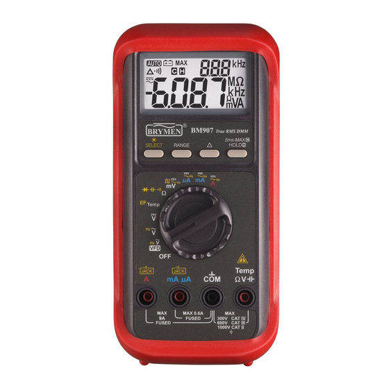
3) PRODUCT DESCRIPTION This user's manual uses only representative model for illustrations. Please refer specification details for function availability to each model. 1) 3-5/6 digits 6000 counts + 999 counts dual display LCD 2) Push-buttons for special functions & features 3) Selector to turn the Power On or Off and select a function... -
Page 5: Operation
4) OPERATION CAUTION Before and after hazardous voltage measurements, test the voltage function on a known source such as line voltage to determine proper meter functioning. VFD-ACV & VFD-Hz (Line Level) Function defaults at VFD-ACV . By default, voltage is set at 600V & 1000V two auto-ranges to best cope with most Variable Frequency Drives (VFD) measurements. - Page 6 & Hz (Line Level) All the voltage and frequency function-ranges within this rotary-switch position are set at regular frequency response without employing LPF. Function defaults at ACV . Hz Input sensitivity varies automatically with voltage range selected. 6V range has the highest and 1000V range has the lowest.
- Page 7 Turn rotary switch to DCV function position directly.
- Page 8 Resistance, Continuity Defaults at . Press SELECT button momentarily to select Continuity function which is convenient for checking wiring connections and operation of switches. A continuous beep tone indicates a complete wire. CAUTION Using Resistance, Continuity, Diode or Capacitance function in a live circuit will produce false results and may damage the instrument.
- Page 9 Diode test Defaults at . Press SELECT button momentarily 3 times to select Diode test function. Normal forward voltage drop (forward biased) for a good silicon diode is between 0.400V to 0.900V. A reading higher than that indicates a leaky diode (defective).
- Page 10 Electric Field EF-Detection Model 905 defaults at E.F. function. Models C. Press SELECT 906s & 907s default at button momentarily 2 times to select E.F. function. The meter displays “E.F.” when it is ready. Signal strength is indicated as a series of bar-graph segments on the display plus variable beep tones.
- Page 11 reading becomes unstable, select higher current range to avoid electrical noise. If the reading shows zero, select lower current range for better sensitivity. CAUTION When measuring a 3-phase system, special attention should be taken to the phase-to-phase voltage which is significantly higher than the phase-to-earth voltage. To avoid exceeding the voltage rating of the protection fuse(s) accidentally, always consider the phase-to-phase voltage as the working voltage for the protection fuse(s).
- Page 12 Relative Zero ( ) mode Relative zero allows the user to offset the meter consecutive measurements with the main display displaying reading as the reference value. Press the button momentarily to toggle relative zero mode. Manual or Auto-ranging Press the RANGE button momentarily to select manual-ranging, and the meter will remain in the range it was in, the LCD turns off.
-
Page 13: Maintenance
5) MAINTENANCE WARNING To avoid electrical shock, disconnect the meter from any circuit, remove the test leads from the input jacks and turn OFF the meter before opening the case. Do not operate with open case. Accuracy and Calibration Accuracy is specified for a period of one year after calibration. Periodic calibration at intervals of one year is recommended to maintain meter accuracy. - Page 14 Battery and Fuse replacement Battery use: Standard 1.5V AAA Size (NEDA 24A or IEC LR03) battery X 2 Fuses use: Fuse (FS1) for AmA current input: 0.4A/1000V ac & dc, IR 30kA, F fuse, or better; Dimension: 6 x 32 mm Fuse (FS2) for A current input: 11A/1000V ac &...
-
Page 15: General Specifications
6) GENERAL SPECIFICATIONS Display: 3-5/6 digits 6000 counts + 3 digits 999 counts dual display LCD Polarity: Automatic Update Rate: 5 per second nominal; Operating Temperature: 0C to 40C Relative Humidity: Maximum relative humidity 80% for temperature up to 31C decreasing linearly to 50% relative humidity at 40C Pollution degree: 2 Storage Temperature: -20C to 60C, <... - Page 16 holster Weight: 340 gm; 430 gm with holster Accessories: Test leads (pair), holster, batteries installed, user's manual Optional Accessories (Models 907s & 906s only): Bkp60 banana plug K-type thermocouple, BKB32 banana plug to type-K socket plug adaptor Special Features: VFD-V & VFD-Hz in Dual Display; Backlighted LCD (Model 907s only);...
- Page 17 DC Current digits for changes > 5ms in duration Burden RANGE Accuracy Voltage RANGE Accuracy 1.2% + 5d 600.0A 0.25mV/A 0.8%+8d 1.0% + 3d 600.0, 6000A 0.25mV/A 60.00mA 2.0% + 5d 4.0mV/mA 6.000K, 60.00K, 0.6%+4d 600.0mA 1.5% + 3d 4.0mV/mA 600.0K...
- Page 18 Hz Line Level Frequency Non-Contact EF-Detection (Dual Display) Bar-Graph Typical Voltage Indication Sensitivity AC Range Range (Sine RMS) 20V (tolerance: 10V ~ 36V) 600mV 0.1V 10Hz~100kHz 55V (tolerance: 23V ~ 83V) 0.6V 10Hz~10kHz 110V (tolerance: 59V ~ 165V) - - - 10Hz~50kHz 220V (tolerance:124V ~ 330V) - - - -...
- Page 19 - NOTE -...
-
Page 20: Limited Warranty
BRYMEN's warranty does not apply to accessories, fuses, fusible resistors, spark gaps, batteries or any product which, in BRYMEN's opinion, has been misused, altered, neglected, or damaged by accident or abnormal conditions of operation or handling.
Need help?
Do you have a question about the BM905s and is the answer not in the manual?
Questions and answers