Table of Contents
Advertisement
C
I
I
URTIS
NSTRUMENTS,
NC.
200 Kisco Avenue
Mt. Kisco, New York 10549 USA
Tel. 914.666.2971
Fax 914.666.2188
www.curtisinstruments.com
12 3 0
MultiMode™ AC INDUCTION
MOTOR CONTROLLER
© 2007 CURTIS INSTRUMENTS, INC.
DESIGN OF CURTIS 1200 SERIES
CONTROLLERS PROTECTED BY U.S.
PATENT NO. 4626750.
1230 Manual, p/n 37092
Rev. C: October 2007
Advertisement
Table of Contents
Troubleshooting

Related Manuals for Curtis Instruments MultiMode 1230


Summary of Contents for Curtis Instruments MultiMode 1230
- Page 1 12 3 0 MultiMode™ AC INDUCTION MOTOR CONTROLLER © 2007 CURTIS INSTRUMENTS, INC. DESIGN OF CURTIS 1200 SERIES CONTROLLERS PROTECTED BY U.S. PATENT NO. 4626750. 1230 Manual, p/n 37092 Rev. C: October 2007 URTIS NSTRUMENTS, 200 Kisco Avenue Mt. Kisco, New York 10549 USA Tel.
- Page 3 CONTENTS CONTENTS 1. OVERVIEW ................1 2. INSTALLATION AND WIRING..........4 Mounting the Controller .............4 Connections: Low Current..........6 Connections: High Current ..........7 Wiring: Standard Configuration A, no multiplexer .....8 Wiring: Standard Configuration B, with multiplexer ..10 Wiring: Standard Configuration C, with multiplexer and a proportional valve on the hydraulic line.....12 Wiring: Throttles ..............14 5kΩ–0 two-wire resistive throttle (“Type 1”)....15...
- Page 4 CONTENTS Sequencing Parameters............30 Interlock Normally Open, Sequencing Delay, SRO, HPD, Main Contactor Interlock Type, Main Contactor Open Delay, Main Contactor Check Brake Parameters..............32 Brake Fault Check, Brake Delay, Brake Hold Voltage, Brake Driver Type, Anti-Rollback Time Emergency Reverse Parameters ..........33 Wiring Check, Speed, Direction Interlock, Time Limit, Accel Rate, Switch Normally Closed Motor &...
- Page 5 CONTENTS Hydraulics Parameters............40 Lift PV Max, Lift PV Min, Lift PV Accel Rate, Lift PV Decel Rate, Lower PV Max, Lower PV Min, Lower PV Accel Rate, Lower PV Decel Rate, PV Dither, Pump Start Delay, Pump BDI Lockout, Lift PV Hold Delay, Load Hold Delay, Open Load Hold During Lift, Hyd Throttle Type, Hyd Throttle Deadband, Hyd Throttle Max, Hyd Throttle Map,...
- Page 6 FIGURES / TABLES FIGURES . 1: Curtis 1230 AC motor controller..........1 . 2: Mounting dimensions, Curtis 1230 controller ......4 . 3: Standard wiring configuration A, for applications without tiller multiplexer ........ 8 . 4: Standard wiring configuration B, for applications with tiller multiplexer ........
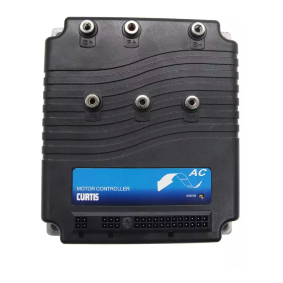
- Page 7 1 — OVERVIEW OVERVIEW The Curtis 1230 motor controller is an AC induction motor speed controller designed for use in a variety of material handling vehicles. Typical applications include walkie/rider pallet trucks, low lifts, stackers, sweeper/scrubber machines, and other small industrial vehicles. This high performance programmable con- troller is simple to install, efficient, and cost effective.
- Page 8 1 — OVERVIEW Like all Curtis motor controllers, the 1230 offers superior operator control of motor speed. Features include: ✓ 60–200 amp AC induction motor controller ✓ MultiMode™ feature allows two distinct user-selectable operation modes ✓ Programmability through the Curtis 1311 handheld programmer and 1314 PC programming station ✓...
- Page 9 1 — OVERVIEW Additional features on 1230-2X01 models (for use with multiplexer) ✓ 4-wire serial interface for all tiller functions ✓ Two auxiliary outputs, controlled by switches on the tiller multiplexer, can be used for a lift relay, lowering valve, horn, etc. ✓...
- Page 10 2 — INSTALLATION & WIRING: Controller INSTALLATION AND WIRING MOUNTING THE CONTROLLER The 1230 controller can be oriented in any position, and meets the IP53 ratings for environmental protection against dust and water. However, the location should be carefully chosen to keep the controller clean and dry. If a clean, dry mounting location cannot be found, a cover must be used to shield the controller from water and contaminants.
- Page 11 2 — INSTALLATION & WIRING: Controller holes provided. Although not usually necessary, a thermal joint compound can be used to improve heat conduction from the controller heatsink to the mounting surface. You will need to take steps during the design and development of your end product to ensure that its EMC performance complies with applicable regulations;...
- Page 12 2 — INSTALLATION & WIRING: Controller CONNECTIONS Low Current Connections Three low current connectors (J1, J2, J3) are built into the 1230 controller. They are located in a row on the top of the controller: 4-pin 6-pin 24-pin The 24-pin connector (J1) provides the logic control connections for the contactor drivers and switches that are wired directly to the vehicle.
- Page 13 2 — INSTALLATION & WIRING: Controller A 6-pin low power Molex connector (J2) is provided for the speed encoder and electromagnetic brake connections. The mating connector is a Molex Mini-Fit Jr. p/n 39-01-2065 using type 5556 terminals. J2 Pin 1 encoder power output J2 Pin 2 encoder A...
- Page 14 2 — INSTALLATION & WIRING: Controller WIRING: Standard Configuration A (no multiplexer) Figure 3 shows the typical wiring configuration for applications where a tiller multiplexer is not used; these applications typically include an external main contactor. For walkie applications the interlock switch is typically activated by the tiller, and an emergency reverse switch on the tiller handle provides the emer- gency reverse signal.
- Page 15 2 — INSTALLATION & WIRING: Controller Power Wiring, Configuration A Motor phase wiring is straightforward, with the motor’s U, V, W phases con- ☞ nected directly to the controller’s studs. The sequence of the CAUTION: C A U T I O N motor phase connections will affect the operation of the emergency reverse feature.
- Page 16 2 — INSTALLATION & WIRING: Controller WIRING: Standard Configuration B (with multiplexer) Figure 4 shows the typical wiring configuration for applications where a tiller multiplexer is used. Most 1230 models designed for use with a multiplexer include an internal main contactor (see specifications in Table C-1); for the 1230-2301 and -2401 models, which do not, the main contactor should be wired as shown in Figure 3.
- Page 17 2 — INSTALLATION & WIRING: Controller Power Wiring, Configuration B Motor phase wiring is straightforward, with the motor’s U, V, W phases con- ☞ nected directly to the controller’s studs. The sequence of the CAUTION: C A U T I O N motor phase connections will affect the operation of the emergency reverse feature.
- Page 18 2 — INSTALLATION & WIRING: Controller WIRING: Standard Configuration C (with multiplexer & PV) Figure 5 shows the typical wiring configuration for applications where a pro- portional valve is used with the tiller multiplexer. Most 1230 models designed for use with a multiplexer include an internal main contactor (see specifications in Table C-1);...
- Page 19 2 — INSTALLATION & WIRING: Controller Power Wiring, Configuration C Motor phase wiring is straightforward, with the motor’s U, V, W phases con- ☞ nected directly to the controller’s studs. The sequence of the CAUTION: C A U T I O N motor phase connections will affect the operation of the emergency reverse feature.
- Page 20 2 — INSTALLATION & WIRING: Throttles WIRING: Throttles Various throttles can be used with the 1230 controller. They are categorized as one of five types in the programming menu of the 13XX programmer. Only Types 2 and 4 can be used for the hydraulic throttle. Type 1: two-wire 5kΩ–0 potentiometer throttles Type 2: 0–5V, current source, and three-wire pot throttles—wired for single-ended operation...
- Page 21 2 — INSTALLATION & WIRING: Throttles 5kΩ–0 Throttle (“Type 1”) The 5kΩ–0 throttle (called a “Type 1” throttle in the programming menu of the 13XX programmer) is a 2-wire resistive throttle that connects between the pot wiper pin (Pin 6) and the Pot Low pin (Pin 7), as shown in Figure 6. For Type 1 devices, zero speed corresponds to a nominal 5 kΩ...
- Page 22 2 — INSTALLATION & WIRING: Throttles the maximum Pot Low current be limited to 55 mA to prevent damage to the Pot Low circuitry. Ground-referenced 0–5V throttles require setting the Pot Low Check parameter (see Section 3, page 28) to Off; otherwise the controller will register a throttle fault.
- Page 23 2 — INSTALLATION & WIRING: Throttles 0–5kΩ Throttle (“Type 3”) The 0–5kΩ throttle (“Type 3” in the programming menu) is a 2-wire resistive throttle that connects between the pot wiper pin and the Pot Low pin, as shown in Figure 10. Zero speed corresponds to 0 Ω measured between the two pins and full speed corresponds to 5 kΩ.
- Page 24 2 — INSTALLATION & WIRING: Aux. Drivers & Emergency Reverse to provide appropriate throttle fault detection. Note: If your Type 4 throttle has an internal neutral switch, this internal neutral switch should be wired to the forward switch input (Pin 13). The controller will behave as though no throttle is requested when the neutral switch is high, and will use the throttle value when the neutral switch is low.
- Page 25 2 — INSTALLATION & WIRING: Emerg. Rev. Check & Spyglass Display automatically driven in the reverse direction at the programmed emergency reverse acceleration rate and speed until the emergency reverse switch is released or the emergency reverse time limit is reached. ☞...
- Page 26 2 — INSTALLATION & WIRING: Tiller Multiplexer & Switches, etc. WIRING: Tiller Multiplexer The Curtis 1312 Multiplexer provides monitoring and control capability for up to 12 analog or digital signals from operator controls on the tiller. Each signal is sampled every 20 milliseconds for fast response. The mating 6-pin connector is Molex 39-01-2065 and the mating 24-pin connector is Molex 39-01-2245, both with 39-00-0039 (18–24 AWG) pins.
- Page 27 2 — INSTALLATION & WIRING: Switches, etc. Main Contactor 1230-2002, -2102, -2202, -23xx, and -24xx models An external main contactor should be used with these models. The contactor allows the controller and motor to be disconnected from the battery. This provides a significant safety feature, because it means battery power can be removed if a controller or wiring fault results in battery power being applied to the motor inappropriately.
- Page 28 2 — INSTALLATION & WIRING: Switches, etc. Electromagnetic Brake The electromagnetic brake, which is usually mounted to the motor shaft, is mechanically engaged by a spring force and electrically released. In wiring configurations A and B, the brake is connected to J2 Pins 3 and 6. The PWM low-side driver at Pin 6 is rated at 2 amps and is monitored for overcurrent faults.
- Page 29 3 — PROGRAMMABLE PARAMETERS PROGRAMMABLE PARAMETERS The 1230 controller has a number of parameters that can be programmed using a Curtis 1311 handheld programmer or 1314 PC programming station. These programmable parameters allow the vehicle’s performance to be customized to fit the needs of individual vehicles or vehicle applications.
- Page 30 3 — PROGRAMMABLE PARAMETERS VEHICLE GROUP MOTOR & CONTROL GROUP SYSTEM GROUP Rate Parameters Motor Parameters Battery Parameters Full Voltage Accel Rate, M1–M2 Min Motor Voltage Decel Rate, M1–M2 Empty Voltage Nominal Motor Voltage BDI Reset Battery Voltage Brake Rate, M1–M2 Nominal Motor Frequency Battery Recharge Level Fast Stop Rate...
- Page 31 3 — PROGRAMMABLE PARAMETERS: Rate Parameters RATE MENU ALLOWABLE PARAMETER RANGE DESCRIPTION M1–M2 Accel Rate 0.1–5.0 sec. Defines the time it takes the controller to accelerate from 0% output to 100% output when full throttle is requested. Larger values represent a lon- ger acceleration time and a gentler start.
- Page 32 3 — PROGRAMMABLE PARAMETERS: Speed Parameters SPEED MENU ALLOWABLE PARAMETER RANGE DESCRIPTION M1–M2 Min Speed 0–50 % Defines the controller output at full throttle when the speed limit pot is in its lowest position or the speed limit switch is calling for minimum speed. M1–M2 Max Speed 5–100 % Defines the controller output at full throttle when the speed limit pot is in...
- Page 33 3 — PROGRAMMABLE PARAMETERS: MultiMode Parameters MULTIMODE MENU ALLOWABLE PARAMETER RANGE DESCRIPTION Mode Select Type 0–3 Configures mode switch operation. 0 = Standard M1/M2 MultiMode operation. When the mode switch is open, the programmed M1 parameter settings for Accel Rate, Decel Rate, Brake Rate, Min Speed, and Max Speed are in effect;...
- Page 34 3 — PROGRAMMABLE PARAMETERS: Throttle Parameters THROTTLE MENU ALLOWABLE PARAMETER RANGE DESCRIPTION Throttle Type 1–5 The 1230 controller accepts a variety of throttle inputs; see throttle wiring section, pages 14–18. The throttle type parameter can be programmed as follows: 2-wire rheostat, 5kΩ–0 input single-ended 3-wire 1kΩ–10kΩ...
- Page 35 3 — PROGRAMMABLE PARAMETERS: Throttle Parameters All three throttle adjustment parameters—Deadband, Max, Map—condition the raw throttle voltage into a single % throttle command, as shown in Figure 14. Fig. 14 Effect of throttle Throttle max parameter adjustment parameters. adjusts this endpoint. Together these three param- THROTTLE MAP eters determine the con-...
- Page 36 3 — PROGRAMMABLE PARAMETERS: Sequencing Parameters SEQUENCING MENU ALLOWABLE PARAMETER RANGE DESCRIPTION Interlock Normally Open When a normally-open type of interlock switch is used, this parameter must be programmed On. Sequencing Delay 0.0–3.0 sec. The sequencing delay feature allows the interlock switch to be cycled within a set time (the sequencing delay), thus preventing inadvertent activation of HPD and SRO.
- Page 37 3 — PROGRAMMABLE PARAMETERS: Sequencing Parameters SEQUENCING MENU, cont’d ALLOWABLE PARAMETER RANGE DESCRIPTION High Pedal Disable (HPD), To meet EEC requirements, HPD Type 1 or Type 2 must be selected. cont’d Sequencing delay (above) can be used to provide a brief delay before HPD inhibits controller output, if desired.
- Page 38 3 — PROGRAMMABLE PARAMETERS: Brake Parameters BRAKE MENU ALLOWABLE PARAMETER RANGE DESCRIPTION Brake Fault Check The brake fault check feature, when programmed On, checks the voltage at the brake output (J2 Pin 6) and faults the controller if this voltage does not correspond to the brake voltage demand.
- Page 39 3 — PROGRAMMABLE PARAMETERS: Emergency Reverse Parameters EMERGENCY REVERSE MENU ALLOWABLE PARAMETER RANGE DESCRIPTION Wiring Check When programmed On, the wiring check tests for continuity from the emergency reverse check output (J1 Pin 16) to the emergency reverse input (J1 Pin 15); see Fig. 4, page 8, for the recommended wiring. This parameter applies only to systems that include the emergency reverse feature.
- Page 40 3 — PROGRAMMABLE PARAMETERS: Motor Control Parameters MOTOR CONTROL PARAMETERS The 1230 controls the motor using a combined V/f and slip control algorithm, which is summarized in Figure 15. Field Weakening slip Motor Frequency Pull Out Slip Slip Boost sync slip P Gain Mod.
- Page 41 3 — PROGRAMMABLE PARAMETERS: Motor Control Parameters MOTOR MENU ALLOWABLE PARAMETER RANGE DESCRIPTION Min Motor Voltage 0.0–6.0 V Defines the starting point of the V/f profile. This voltage is applied to the motor at 0 RPM if no (or very low) torque is demanded. Increasing this parameter can improve low speed behavior, because the motor will have flux even at zero throttle request.
- Page 42 3 — PROGRAMMABLE PARAMETERS: Motor Control Parameters CONTROL MENU ALLOWABLE PARAMETER RANGE DESCRIPTION P Gain 0.00–1.00 The proportional gain and integral gain parameters define the gain of the proportional and integral fractions of the PI slip control. The optimum set- tings of these parameters depend on the mechanical design of the vehicle and drive train, which means they must be adjusted empirically through experimental testing.
- Page 43 3 — PROGRAMMABLE PARAMETERS: Motor Control Parameters Fig. 16 Motor control pa- rameters and their effect on CONSTANT CONSTANT TORQUE HIGH SPEED POWER operating characteristics. Field Weakening MOTOR Accel Compensation VOLTAGE (rms) Full Load Accel Slip Voltage No Load Min Motor Voltage FREQUENCY Nominal Motor...
- Page 44 3 — PROGRAMMABLE PARAMETERS: Battery Parameters BATTERY MENU ALLOWABLE PARAMETER RANGE DESCRIPTION Full Battery Voltage – Sets the voltage at or above which 100% charge is indicated on the BDI display. The allowable range is from the programmed Empty Battery Voltage [FBV] up to the BDI Reset Battery Voltage, in VPC (volts per cell) units.
- Page 45 3 — PROGRAMMABLE PARAMETERS: Hourmeter Parameters HOURMETER MENU ALLOWABLE PARAMETER RANGE DESCRIPTION Enable Total Service Hours When programmed Off, the total hourmeter will continue to count the total hours of operation (i.e., KSI on-time) but no action will be taken when the service interval elapses.
- Page 46 3 — PROGRAMMABLE PARAMETERS: Hydraulics Parameters HYDRAULICS PARAMETERS In standard wiring configuration A (page 8), the 1230 provides a feed-through for hydraulics control signals, but otherwise has no relationship to the hydrau- lics system. In standard wiring configuration B (page 10), the 1230 turns the pump motor on and off, and opens and shuts the lowering valve;...
- Page 47 3 — PROGRAMMABLE PARAMETERS: Hydraulics Parameters HYDRAULICS MENU ALLOWABLE PARAMETER RANGE DESCRIPTION Lift PV Max 0–100 % Defines the PWM output to the proportional valve for a Lift request with full hydraulic throttle applied. Lower values provide faster Lift, by allowing less of the hydraulic fluid to be diverted from the Lift operation.
- Page 48 3 — PROGRAMMABLE PARAMETERS: Hydraulics Parameters HYDRAULICS MENU, cont’d ALLOWABLE PARAMETER RANGE DESCRIPTION Lift PV Hold Delay 0.00–1.00 sec. Defines how long the PV stays open at the end of a lift operation to allow the pump to stop before the valve closes. Load Hold Delay 0.00–1.00 sec.
- Page 49 3 — PROGRAMMABLE PARAMETERS: Other System Parameters OTHER SYSTEM PARAMETERS MENU ALLOWABLE PARAMETER RANGE DESCRIPTION Power Save Delay 0–240 min. Defines the time the controller will remain in standby* before switching to power save mode; the controller will leave power save mode and resume normal operation as soon as the interlock switch is closed or the keyswitch is cycled.
- Page 50 3 — PROGRAMMABLE PARAMETERS: Cloning Controllers OTHER SYSTEM PARAMETERS MENU, cont’d ALLOWABLE PARAMETER RANGE DESCRIPTION Fault Code Configures the status LED driver (J1 Pin 17) to display fault information in Fault Code format or Fault Category format: On = Fault Code format The status LED driver provides a pulsed signal equivalent to the fault code flashed by the controller’s built-in status LED;...
- Page 51 4 — MONITOR MENU MONITOR MENU Through the monitor menu, the 13XX programmers provide access to real-time data during vehicle operation. This information is helpful during diagnostics and troubleshooting, and also during programmable parameter adjustment. MONITOR MENU ITEM VALUE DISPLAYED MOTOR + BATTERY Battery Voltage Voltage at KSI, in volts.
- Page 52 5 — INITIAL SETUP INITIAL SETUP It is imperative that these initial setup procedures be carefully followed to ensure that the controller is set up to be compatible with your application. Do not drive the vehicle until initial setup has been completed. The following information should be obtained from the motor label or from the motor manufacturer: •...
- Page 53 5 — INITIAL SETUP Control setup (see page 36) Use these guidelines to set the parameters in the Control menu initially: RECOMMENDED INITIAL CONTROL PARAMETER SETTINGS PARAMETER INITIAL SETTING P Gain I Gain Accel Slip Motor Frequency – (Motor Poles × Motor Speed / 120); typically 3 –...
- Page 54 5 — INITIAL SETUP Tuning the Throttle Deadband 3-a. Make sure the interlock switch is open, and turn on the keyswitch. 3-b. Observe the Monitor > Inputs > Throttle Input parameter; you will need to reference the value displayed here. 3-c.
- Page 55 5 — INITIAL SETUP Initial adjustment of motor control parameters (see pages 36 and 37) The performance of an AC induction motor is significantly influenced by temperature. Therefore, the following procedure should be performed with a warm motor. 4-a. With the interlock switch closed, select a direction and apply throttle. The motor should begin to turn in the selected direction.
- Page 56 5 — INITIAL SETUP Fine tuning of motor control parameters (see page 36) This procedure is conducted after the vehicle is taken down off the blocks. If a motor or vehicle test bench is available, is should be used for this procedure as it is the easiest and most accurate way to make these adjustments.
- Page 57 6 — VEHICLE PERFORMANCE ADJUSTMENT VEHICLE PERFORMANCE ADJUSTMENT The 1230 controller’s wide variety of adjustable parameters allows many aspects of vehicle performance to be optimized. This section provides explanations of what the major tuning parameters do and instructions on how to use these parameters to optimize the performance of your vehicle.
- Page 58 6 — VEHICLE PERFORMANCE ADJUSTMENT > Throttle), see pages 28–29. This procedure adjusts characteristics related to the “feel” of the vehicle. 8-a. Speed (Speed Limit Type, M1/M2 Max Speed, M1/M2 Min Speed). First, set the Speed Limit Type parameter to match the type of speed limit input your application will use.
- Page 59 6 — VEHICLE PERFORMANCE ADJUSTMENT Hydraulic system tuning Tuning the hydraulic system is more straightforward than tuning the drive sys- tem, because the parameters are not as inter-related. Nonetheless, it is important that the effect of these programmable parameters be understood; please refer to the description of the hydraulic parameters on pages 39–41.
- Page 60 7 — DIAGNOSTICS & TROUBLESHOOTING DIAGNOSTICS AND TROUBLESHOOTING Diagnostic information is provided by the fault codes flashed by the Status LED, the fault display on the Spyglass gauge, and the Faults menu on the 1311 programmer. Refer to the troubleshooting chart at the end of this section for suggestions covering a wide range of possible faults.
- Page 61 7 — DIAGNOSTICS & TROUBLESHOOTING LED Fault Categories In the “fault category” format, the LED indicates one of three categories. Be- cause the category does not provide diagnostic information, you will need to use the programmer to find out what the problem is. Table 4 STATUS LED FAULT CATEGORIES CATEGORY INDICATION...
- Page 62 7 — DIAGNOSTICS & TROUBLESHOOTING Table 5 TROUBLESHOOTING CHART PROGRAMMER CODE EXPLANATION POSSIBLE CAUSE LCD DISPLAY Motor Speed Encoder Motor speed encoder pulses 1. Incorrect encoder wiring. are not correct. 2. Controller defective. Motor Failsafe Motor stalled, or motor turning 1.
- Page 63 7 — DIAGNOSTICS & TROUBLESHOOTING Table 5 TROUBLESHOOTING CHART, continued PROGRAMMER CODE EXPLANATION POSSIBLE CAUSE LCD DISPLAY Brake Fault Brake wiring or driver fault. 1. Brake coil open. 2. Brake missing. 3. Wire to brake missing. 4. Brake driver shorted. Service Total Disabled Total disable timer has expired.
- Page 64 8 — MAINTENANCE MAINTENANCE There are no user serviceable parts in the Curtis 1230 controller. No attempt should be made to open, repair, or otherwise modify the controller. Doing so may damage the controller and will void the warranty. It is recommended that the controller and connections be kept clean and dry and that the controller’s diagnostics history file be checked and cleared periodically.
- Page 65 APPENDIX A: EMC & ESD DESIGN CONSIDERATIONS APPENDIX A VEHICLE DESIGN CONSIDERATIONS REGARDING ELECTROMAGNETIC COMPATIBILITY (EMC) AND ELECTROSTATIC DISCHARGE (ESD) ELECTROMAGNETIC COMPATIBILITY (EMC) Electromagnetic compatibility (EMC) encompasses two areas: emissions and immunity. Emissions are radio frequency (rf ) energy generated by a product. This energy has the potential to interfere with communications systems such as radio, television, cellular phones, dispatching, aircraft, etc.
- Page 66 APPENDIX A: EMC & ESD DESIGN CONSIDERATIONS Conducted paths are created by the wires connected to the controller. These wires act as antennas and the amount of rf energy coupled into them is generally proportional to their length. The rf voltages and currents induced in each wire are applied to the controller pin to which the wire is connected.
- Page 67 APPENDIX A: EMC & ESD DESIGN CONSIDERATIONS can be reduced by filtering the wire where it passes through the shield boundary. Given the safety considerations involved in connecting electrical components to the chassis or frame in battery powered vehicles, such filtering will usually consist of a series inductor (or ferrite bead) rather than a shunt capacitor.
- Page 68 APPENDIX B: PROGRAMMER OPERATION & MENUS APPENDIX B PROGRAMMERS Curtis programmers provide programming, diagnostic, and test capabilities for the 1230 controller. The power for operating the programmer is supplied by the host controller via a 4-pin connector. Two programmers are available: the PC Programming Station (1314) and the handheld programmer (1311).
- Page 69 APPENDIX B: PROGRAMMER OPERATION & MENUS information from the controller. For experimenting with settings, the program- mer can be left plugged in while the vehicle is driven. The bookmark keys can make parameter adjustment more convenient. For example, in setting the throttle deadband parameter, you might set a bookmark at this parameter in the Throttle submenu [Program >...
- Page 70 APPENDIX C: SPECIFICATIONS APPENDIX C SPECIFICATIONS Table C-1 SPECIFICATIONS: 1230 CONTROLLER Operating voltage range 16 to 32V Nominal input voltage 24 V PWM operating frequency 16 kHz Electrical isolation to heatsink 500 V ac (minimum) KSI input current (no contactors engaged) 90 mA without programmer or speed encoder 170 mA with programmer and SKF speed encoder Logic input voltage...
Need help?
Do you have a question about the MultiMode 1230 and is the answer not in the manual?
Questions and answers
lind T14 muss beim Batterie Wechsel die Curtis 1230 neu programmiert werden