Table of Contents
Advertisement
Manual
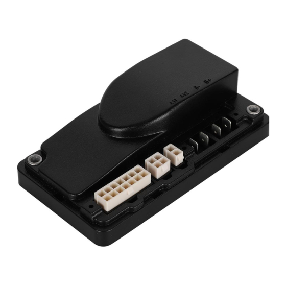
Models 1212 & 1212P
Electronic Motor Controllers
Curtis Instruments, Inc.
200 Kisco Avenue
Mt. Kisco, NY 10549
www.curtisinstruments.com
Read Instructions Carefully!
Specifications are subject to change without notice.
© 2019 Curtis Instruments, Inc. ® Curtis is a registered trademark of Curtis Instruments, Inc.
© The design and appearance of the products depicted herein are the copyright of Curtis Instruments, Inc.
53112 Rev F Sep 2019
Advertisement
Table of Contents
Troubleshooting

Related Manuals for Curtis Instruments 1212


Summary of Contents for Curtis Instruments 1212
- Page 1 Specifications are subject to change without notice. © 2019 Curtis Instruments, Inc. ® Curtis is a registered trademark of Curtis Instruments, Inc. © The design and appearance of the products depicted herein are the copyright of Curtis Instruments, Inc. 53112 Rev F Sep 2019...
-
Page 2: Table Of Contents
STALL PARAMETERS ........................23 BDI PARAMETERS ........................24 COMPENSATION PARAMETERS ....................25 EMERGENCY REVERSE PARAMETES ..................... 25 MISCELLANEOUS PARAMETERS ....................26 4: MONITOR MENU ..........................27 5: INITIAL SETUP ..........................28 pg. ii 1212 & 1212P Manual - Sep 2019... - Page 3 FIGURE 1: CURTIS 1212/1212P ELECTRONIC MOTOR CONTROLLER ........... 1 FIGURE 2: MOUNTING DIMENSIONS, CURTIS 1212/1212P CONTROLLERS .......... 4 FIGURE 3A: STANDARD WIRING CONFIGURATION, CURTIS 1212 CONTROLLER ........6 FIGURE 3B: STANDARD WIRING CONFIGURATION, CURTIS 1212P CONTROLLER ........7 FIGURE 4: WIRING FOR 3-WIRE, 5KΩ POTENTIOMETER THROTTLE ............8 FIGURE 5: WIRING FOR VOLTAGE THROTTLE ..................
- Page 4 TABLE OF CONTENTS CONT’D TABLES TABLE 1: PROGRAMMABLE PARAMETER MENUS ................13 TABLE 2: STATUS LED FAULT CODES ....................38 TABLE 3: TROUBLESHOOTING CHART ....................39 TABLE E-1: SPECIFICATIONS: 1212 CONTROLLER ................48 pg. iv 1212 & 1212P Manual - Sep 2019...
-
Page 5: 1: Overview
The Curtis 1212 and 1212P motor speed controllers provide precise and smooth control of permanent magnet drive motors for battery powered vehicles. The 1212 is designed for use in low power DME applications such as micro-scooters, mini-scooters, foldable scooters, and low-end personal mobility vehicles. - Page 6 • Industry standard footprint, mounting centers, and wiring allows drop-in replacement of other controllers • 1212 and 1212P controllers are easily programmed with a Curtis programming device, or can be supplied pre-programmed • Accepts all standard throttle types, including single-ended, wigwag, and unipolar •...
- Page 7 Meets or Complies with Relevant US and International regulations • 1212 is designed to meet EN 12184, EN 55022, IEC 61000-6-2 & -4-6, and ISO 7176; FDA documentation filed; TÜV certification pending. • 1212P designed to meet EN 12895, EN 1175, EN 13849, and UL583.
-
Page 8: 2: Installation And Wiring
INSTALLATION AND WIRING MOUNTING THE CONTROLLER The 1212/1212P controller can be oriented in any position, but the location should be carefully chosen to keep the controller clean and dry. If a clean, dry mounting location cannot be found, a cover must be used to shield the controller from water and contaminants. -
Page 9: Connections: High Current
1212 & 1212P Manual - Sep 2019 Return to TOC CONNECTIONS: High Current Four 1/4" Faston terminals are provided for the high current connections. The motor connections M1, M2 and battery connections (B+, B–) have one terminal each. CONNECTIONS: Low Current The low current logic control connections are provided by a 14-pin connector. -
Page 10: Wiring: Standard Installation, 1212
1212 & 1212P Manual - Sep 2019 Return to TOC WIRING: STANDARD INSTALLATION, 1212 The wiring diagram presented in Figure 3a shows a typical installation for a DME application. This installation is shown with a single-ended 3-wire 5kΩ potentiometer throttle and a reverse switch. -
Page 11: Wiring: Standard Installation, 1212P
1212 & 1212P Manual - Sep 2019 Return to TOC WIRING: STANDARD INSTALLATION, 1212P The wiring diagram presented in Figure 3b shows a typical installation for a pallet truck application. This installation is shown with a Curtis electronic throttle. The inhibit input can be wired into the circuit in various ways;... -
Page 12: Throttle Wiring
Return to TOC THROTTLE WIRING Either a 3-wire potentiometer throttle or a voltage throttle can be used with the 1212/1212P controller. The controller can accept a single-ended, inverse single-ended, wigwag, inverse wigwag, or unipolar input signal from the throttle, depending on how the Throttle Type parameter is programmed;... -
Page 13: Figure 5: Wiring For Voltage Throttle
1212 & 1212P Manual - Sep 2019 Return to TOC Voltage Throttle Wiring for a voltage throttle is shown in Figure 5. With this throttle, the controller can be programmed for a Throttle Type 5–9 input signal; see page Figure 5... -
Page 14: Switches And Other Hardware
1212 & 1212P Manual - Sep 2019 Return to TOC SWITCHES AND OTHER HARDWARE Keyswitch The vehicle should have a master on/off switch to turn the system off when not in use. The keyswitch provides logic power for the controller and for the other control input switches. It must be sized to carry the 150 mA quiescent logic current plus the current necessary to drive the precharge function (1.5 A for 0.5 seconds) and the status LED, horn, and any other accessories powered from the... -
Page 15: Figure 6: Wiring To Inhibit Operation During Battery Charging
Return to TOC Battery Discharge Indicator (BDI) The 1212/1212P controller can drive a BDI panel meter to show the battery pack’s state of charge as a percentage of the ampere-hour capacity of the batteries. The batteries must be put through a full charge cycle with the controller installed before the BDI will begin operation. - Page 16 Return to TOC Status LED The 1212/1212P controller has the capability to drive a panel indicator LED, which can be used to tell the operator, at a glance, the controller’s status. This LED always indicates whether the controller is powered on or off. It will also provide diagnostics information via flash codes (see Section 7).
-
Page 17: 3: Programmable Parameters
Return to TOC 3 — PROGRAMMABLE PARAMETERS The 1212/1212P controllers have a number of parameters that can be programmed using a Curtis handheld programmer or Curtis PC Programming Station. These programmable parameters allow the vehicle’s performance to be customized to best fit the needs of individual vehicle operators. - Page 18 1212 & 1212P Manual - Sep 2019 Return to TOC Table 1 Programmable Parameter Menus: 1311 Programmer, cont’d BDI MENU........p. 24 EMERGENCY REVERSE MENU.... p. 25 — Full Voltage — Speed — Empty Voltage — Time Limit — Full Charge Voltage —...
-
Page 19: Drive Parameters
1212 & 1212P Manual - Sep 2019 Return to TOC DRIVE MENU PARAMETER ALLOWABLE RANGE DESCRIPTION Accel Max Speed 0.2–8.0 s Sets the rate (in seconds) at which the speed command increases when throttle is applied with the speed limit pot is in its maximum speed position, and the vehicle is traveling forward. - Page 20 1212 & 1212P Manual - Sep 2019 Return to TOC DRIVE MENU, cont’d PARAMETER ALLOWABLE RANGE DESCRIPTION Gear Soften 0–100 % This parameter is intended to soften the bump associated with gear slack in the transaxle when throttle is released and then reapplied while the vehicle is still moving.
-
Page 21: Speed Parameters
1212 & 1212P Manual - Sep 2019 Return to TOC SPEED MODES The 1212/1212P controller’s Multi-Mode feature allows operation in two distinct modes: Mode 1 and Mode 2. These modes can be programmed to provide two different sets of operating characteristics, which can be useful for operation in different conditions. -
Page 22: Throttle Parameters
ALLOWABLE RANGE DESCRIPTION Type 0–9 The 1212/1212P controller can accept inputs from both 5kΩ, 3-wire pot throttles and voltage throttles. Set the throttle type parameter to match the throttle used in your application. 5kΩ, 3-wire pot throttles 0 = wigwag 1 = inverted wigwag 2 = single-ended;... -
Page 23: Figure 7: Effect Of Adjusting The Throttle Map Parameter
1212 & 1212P Manual - Sep 2019 Return to TOC THROTTLE MENU, cont’d PARAMETER ALLOWABLE RANGE DESCRIPTION Speed Limit Pot On/Off This parameter is used to enable/disable the speed limit pot. If no speed limit pot is used, set Speed Limit Pot to Off. - Page 24 1212 & 1212P Manual - Sep 2019 Return to TOC THROTTLE MENU, cont’d PARAMETER ALLOWABLE RANGE DESCRIPTION Calibration On/Off Wigwag and unipolar throttle pots should be centered. Setting this parameter to On inhibits driving and puts the controller into throttle autocalibration mode;...
-
Page 25: Current Parameters
For 1212-22xx controllers, it is adjustable from 10 to 45 amperes. For 1212-24xx controllers, it is adjustable from 15 to 70 amperes. -
Page 26: Brake Parameters
1212 & 1212P Manual - Sep 2019 Return to TOC BRAKE MENU PARAMETER ALLOWABLE RANGE DESCRIPTION Delay 0–1 s Sets the length of delay between when zero speed is commanded and the electromagnetic brake is engaged. Fault Check On/Off Enables/disables the fault detection on the EM brake. -
Page 27: Motor Parameters
DESCRIPTION Stall Speed 0–255 1212 only. Sets the Stall Speed that will be used to determine a Motor Stalled fault. A Motor Stalled fault is issued when the estimated speed < Stall Speed and the duty cycle is < Stall PWM for longer than Stall Timeout. -
Page 28: Bdi Parameters
1212 & 1212P Manual - Sep 2019 Return to TOC The Battery menu allows any lead acid battery to be installed and the BDI algorithm tailored to match it. Actual usage duty cycle greatly affects the settings and the overall accuracy of the BDI algorithm. -
Page 29: Compensation Parameters
1212 & 1212P Manual - Sep 2019 Return to TOC COMPENSATION MENU PARAMETER ALLOWABLE RANGE DESCRIPTION IR Comp 0–100 % Sets the motor load compensation. Higher values provide stronger disturbance rejection, while lower values provide smoother operation. Note: Allowable range is restricted by the Anti-Rollback Comp setting. -
Page 30: Miscellaneous Parameters
1212 & 1212P Manual - Sep 2019 Return to TOC MISCELLANEOUS MENU PARAMETER ALLOWABLE RANGE DESCRIPTION Sleep 0–60 minutes Sets the delay time between the last throttle request or serial communication and when the controller goes into sleep mode. Setting the delay to zero disables the sleep function. -
Page 31: 4: Monitor Menu
1212 & 1212P Manual - Sep 2019 Return to TOC 4 — MONITOR MENU Through its Monitor menu, the 1311 programmer provides access to real-time data during vehicle operation. This information is helpful during diagnostics and troubleshooting, and also while adjusting programmable parameters. -
Page 32: 5: Initial Setup
1212 & 1212P Manual - Sep 2019 Return to TOC 5 — INITIAL SETUP Before operating the vehicle, carefully complete the following initial setup procedures. If you find a problem during the checkout, refer to the diagnostics and troubleshooting section (Section 7) for further information. - Page 33 1212 & 1212P Manual - Sep 2019 Return to TOC Tuning the Throttle Max c. Apply full throttle and observe the Throttle value. This value should be 100%. If it is less than 100%, the Throttle Max value should be decreased to get 100% throttle. After entering a smaller Throttle Max value (Program »...
- Page 34 (1212-22xx models) or to 35 amps (1212-24xx and 1212P models). d. Set the Boost Current Limit parameter (Program » Current » Boost Current Limit) to the same value as the Main Current Limit: 25 amps for 1212-22xx models, and 35 amps for 1212-24xx and 1212P models.
-
Page 35: 6: Vehicle Performance Adjustment
Return to TOC 6 — VEHICLE PERFORMANCE ADJUSTMENT The 1212/1212P controller’s adjustable parameters allow many aspects of vehicle performance to be optimized. Once a vehicle/motor/controller combination has been tuned, the parameter values can be made standard for that system or vehicle model. Any changes in the motor, the vehicle drive system, or the controller will require that the system be tuned again to provide optimum performance. - Page 36 1212 & 1212P Manual - Sep 2019 Return to TOC Step 6: Setting the acceleration and deceleration rates The acceleration and deceleration functions have been designed to provide smooth throttle response when maneuvering at low speeds and snappy throttle response when traveling at high speeds. This is accomplished by defining acceleration/deceleration rates at each end of the speed limit pot’s...
- Page 37 1212 & 1212P Manual - Sep 2019 Return to TOC Fine tuning the acceleration and deceleration rates Drive around in both Mode 1 and Mode 2, while varying the position of the throttle and the speed limit pot. In most cases, setting the acceleration and deceleration rates as described in Steps 6-a through 6-h will provide good performance throughout.
- Page 38 1212 & 1212P Manual - Sep 2019 Return to TOC Step 7: Adjusting IR compensation The IR Comp parameter is used to set the percentage of the maximum motor resistance that will be applied, i.e., (IR Comp) × (System Resistance), to compensate for increased load caused by uneven terrain.
- Page 39 1212 & 1212P Manual - Sep 2019 Return to TOC Step 8: Fine-tuning the vehicle’s response smoothness Three additional parameters—Gear Soften, Soft Start, and Tremor Suppression—are available for softening and smoothing vehicle response. In most cases, these functions can be used to provide smooth vehicle operation while still maintaining a high degree of responsiveness.
- Page 40 1212 & 1212P Manual - Sep 2019 Return to TOC Tremor Suppression Tremor Suppression adjusts vehicle response to sharp throttle movements, such as those resulting inadvertently from hand tremors. This parameter can be set from 0–100%, with larger values providing steadier response. The tremor compensation function somewhat overlaps the gear softening functions.
-
Page 41: 7: Diagnostics And Troubleshooting
Return to TOC 7 — DIAGNOSTICS AND TROUBLESHOOTING The 1212 and 1212P controllers provide diagnostics information to assist technicians in troubleshooting drive system problems. The diagnostics information can be obtained in two ways: by reading the appropriate display on the programmer or by observing the fault codes issued by the status LED. -
Page 42: Table 2 Status Led Fault Codes
1212 & 1212P Manual - Sep 2019 Return to TOC Table 2 Status LED Fault Codes LED CODES FAULT LED off no power or defective controller solid on controller powered up; no faults ¤ ¤ THERMAL FAULT ¤ ¤¤ THROTTLE FAULT ¤... -
Page 43: Table 3 Troubleshooting Chart
1212 & 1212P Manual - Sep 2019 Return to TOC Table 3 TROUBLESHOOTING CHART PROGRAMMER CODE LCD DISPLAY EXPLANATION POSSIBLE CAUSE over-/under-temperature cutback 1. Temperature >80°C or < -10°C. 2. Excessive load on vehicle. THERMAL FAULT 3. Operation in extreme environments. -
Page 44: 8: Maintenance
Return to TOC 8 — MAINTENANCE There are no user serviceable parts in Curtis 1212/1212P controllers. No attempt should be made to open, repair, or otherwise modify the controller. Doing so may damage the controller and will void the warranty. However, it is recommended that the controller’s fault history file be checked and cleared periodically, as part of routine vehicle maintenance. -
Page 45: Appendix A: Vehicle Design Considerations
1212 & 1212P Manual - Sep 2019 Return to TOC APPENDIX A VEHICLE DESIGN CONSIDERATIONS REGARDING ELECTROMAGNETIC COMPATIBILITY (EMC) Electromagnetic compatibility (EMC) encompasses two areas: emissions and immunity. Emissions are radio frequency (RF) energy generated by a product. This energy has the potential to interfere with communications systems such as radio, television, cellular phones, dispatching, aircraft, etc. - Page 46 1212 & 1212P Manual - Sep 2019 Return to TOC In some applications, the vehicle designer will need to mount the controller within a shielded box on the end product. The box can be constructed of just about any metal, although steel and aluminum are most commonly used.
-
Page 47: Appendix B: En 13849 Compliance, Curtis 1212P Controller
1212 & 1212P Manual - Sep 2019 Return to TOC APPENDIX B EN 13849 COMPLIANCE, CURTIS 1212P CONTROLLER Since January 1, 2012, conformance to the European Machinery Directive has required that the Safety Related Parts of the Control System (SRPCS) be designed and verified upon the general principles outlined in EN13849. - Page 48 1212 & 1212P Manual - Sep 2019 Return to TOC Curtis has analyzed each safety function and calculated its Mean Time To Dangerous Failure (MTTFd) and Diagnostic Coverage (DC), and designed them against Common Cause Faults (CCF). The safety-related performance of the Curtis 1212P is summarized as follows:...
-
Page 49: Appendix C: Battery Discharge Indicator (Bdi) Setup
APPENDIX C BATTERY DISCHARGE INDICATOR (BDI) SETUP The Battery Discharge Indicator used with the 1212/1212P is quite flexible and, once set up, will provide the user with reliable information on the status of the battery system. The BDI parameters (Program » BDI menu) must be set up specifically for the type and size of the charger, the battery size, and the vehicle’s expected drive cycle. - Page 50 BDI gauge to respond to partial charging. The traditional method is to require a full recharge and not to reset the BDI gauge until the battery is full. The 1212/1212P can also be programmed to allow the user to stop the charge in mid-cycle and display a proportional amount of charge, or “partial charge”...
-
Page 51: Appendix D: Programming Devices
APPENDIX D PROGRAMMING DEVICES Curtis programmers provide programming, diagnostic, and test capabilities for the 1212/1212P controllers. The power for operating the programmer is supplied by the host controller via a 4-pin connector. When the programmer powers up, it gathers information from the controller. -
Page 52: Appendix E: 1212/1212P Controller Specifications
Weight 0.3 kg (0.7 lbs) Dimensions (W×L×H) 72 × 131 × 39 mm (2.8" × 5.2" × 1.5") Regulatory compliance, 1212 Designed to meet EN 12184, EN 55022, IEC 61000-6-2 & -4-6, and ISO 7176 FDA documentation filed TÜV Certification pending.
Need help?
Do you have a question about the 1212 and is the answer not in the manual?
Questions and answers
при включении питания загораются и тухнут индикаторы и после 3 секунд
Здравствуйте! Оборвали провод от кнопки питания как правильно подключить
To properly connect the power button wire for Curtis Instruments part number 1212, connect the keyswitch input (power button) to terminal J1-5 (KSI). This allows power to flow when the button is activated. Ensure a fuse is installed between the battery positive (B+) and J1-5 for protection.
This answer is automatically generated
@Mr. Anderson
Спасибо с красной кнопкой разобрался ,Еще с этой кнопкой включения находится магнитный включатель куда его подключать? И если можно отправьте схему подключения проводов от аккумулятора , провод 3-5-30 31
Оборвали провода от кнопки включения и магнитного выключателя кто подскажет куда они подключаются
For Curtis Instruments part number 1212, the wire from the power button (keyswitch) connects to J1-5 (KSI), and the magnetic (electromagnetic) brake switch connects to the J3 connector: Brake + to J3 Pin 1 and Brake – to J3 Pin 2.
This answer is automatically generated
Подскажите пожалуйста куда подключаются провода от кнопки электротелеги