Table of Contents
Advertisement
CURTIS PMC
235 East Airway Boulevard
Livermore, California 94568 USA
Tel: 925-961-1088
Fax: 925-961-1099
www.curtisinst.com
MANUAL
1209B/1221B
1221C/1231C
MOTOR CONTROLLERS
© 1999 CURTIS INSTRUMENTS, INC.
DESIGN OF CURTIS PMC 1200 SERIES
CONTROLLERS PROTECTED BY U.S.
PATENT NO. 4626750.
1209B/1221B/1221C/1231C Manual
p/n 98827, Rev. D: August 1999
Advertisement
Table of Contents
Troubleshooting

Related Manuals for Curtis Instruments PMC 1200 Series


Summary of Contents for Curtis Instruments PMC 1200 Series
- Page 1 MANUAL 1209B/1221B 1221C/1231C MOTOR CONTROLLERS © 1999 CURTIS INSTRUMENTS, INC. DESIGN OF CURTIS PMC 1200 SERIES CONTROLLERS PROTECTED BY U.S. PATENT NO. 4626750. CURTIS PMC 235 East Airway Boulevard 1209B/1221B/1221C/1231C Manual Livermore, California 94568 USA p/n 98827, Rev. D: August 1999...
- Page 2 1209B / 1221B / 1221C / 1231C Manual p/n 98827, Rev. D: August 1999 © 1999 CURTIS INSTRUMENTS, INC. This electronic version of the 1209B/1221B/1221C/1231C manual is offered as a convenience to our customers. You may download any or all of it.
-
Page 3: Table Of Contents
CONTENTS 1 2 3 4 5 6 7 8 9 0 1 1 2 3 4 5 6 7 8 9 0 1 CONTENTS 1 2 3 4 5 6 7 8 9 0 1 1 2 3 4 5 6 7 8 9 0 1 1 2 3 4 5 6 7 8 9 0 1 1 2 3 4 5 6 7 8 9 0 1 1 2 3 4 5 6 7 8 9 0 1... - Page 4 CONTENTS 1 2 3 4 5 6 7 8 9 0 1 2 3 4 5 6 7 8 9 0 MAINTENANCE AND ADJUSTMENT ....... 24 1 2 3 4 5 6 7 8 9 0 1 2 3 4 5 6 7 8 9 0 1 2 3 4 5 6 7 8 9 0 1 2 3 4 5 6 7 8 9 0 Controller ..............
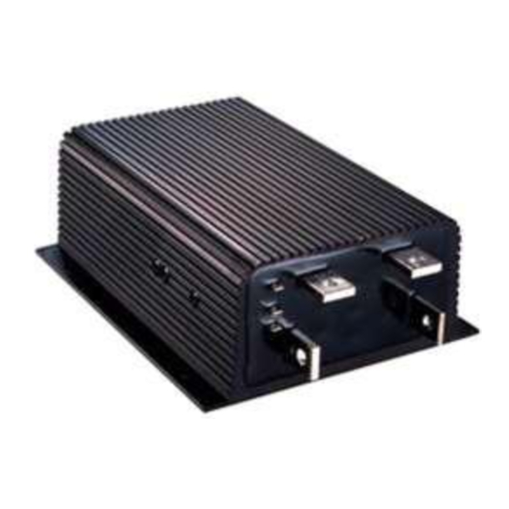
- Page 5 FIGURES FIGURES . 1: Curtis PMC 1209B full-feature motor controller ............1 . 2: Mounting dimensions, Curtis PMC 1209B/1221B/1221C controllers ... 3 . 3: Mounting dimensions, Curtis PMC 1231C controller ........4 . 4: Mounting dimensions, Curtis PMC potboxes PB-5, -6, -9, and -10 ....6 .
- Page 6 FIGURES/TABLES . 14: Curtis electronic throttle (ET series) with a controller having the optional 0–5V throttle input ..........19 . 15: Reduced speed operation (with standard (0–5kΩ pot) ............. 20 . 16: Throttle ramp shapes ..........21 . 17: Adjustment pots ............25 .
-
Page 7: Overview
Models 1221B, 1221C, and 1231C have similar external connections. Like all Curtis PMC 1200 series controllers, the 1209B/1221B/1221C/1231C models offer superior operator control of the vehicle’s motor drive speed. Key features of these controllers include: ✓ Infinitely variable drive and brake control ✓... - Page 8 OVERVIEW ✓ Undervoltage cutback function protects against low battery voltage, includ- ing low voltage caused by external loads ✓ Throttle pot fault circuitry shuts off the motor in the event of an open circuit fault in the throttle or its wiring, to prevent runaway conditions ✓...
-
Page 9: Hardware Installation
HARDWARE INSTALLATION HARDWARE INSTALLATION CONTROLLER The controller can be oriented in any position, but the location should be carefully chosen to keep the controller as clean and dry as possible. If a clean, dry mounting location cannot be found, a cover must be used to deflect dirt and water splash. - Page 10 HARDWARE INSTALLATION Be sure to mount the 1209B/1221B/1221C controller so as to allow access to the adjustment screws. Although not usually necessary, a thermal joint compound can be used to improve heat conduction from the case to the mounting surface. 1231C The controller should be fastened to a clean, flat metal surface that provides an adequate heat sink.
-
Page 11: Throttle
HARDWARE INSTALLATION Six mounting clamps are provided, which can be used to attach the control- ler to its matching heatsink (Curtis PMC p/n 16421001) or to some other surface. An alternative mounting method is provided by six tapped holes on the bottom of the controller. -
Page 12: Fig . 4: Mounting Dimensions
HARDWARE INSTALLATION Mounting Fig. 4 45 ° dimensions, 42 (1.65) Curtis PMC potboxes PB-5, -6, -9, and -10. 10 (0.38) (2.37) (1.25) 89 (3.5) 52 (2.06) (0.25) 102 (4.0) RIGHT-HAND OPERATION LEFT-HAND OPERATION N.C. N.O. COM. COM. N.O. N.C. WITH MICROSWITCH: PB-6 WITH MICROSWITCH: PB-9 WITHOUT MICROSWITCH: PB-5 WITHOUT MICROSWITCH: PB-10... -
Page 13: Fig . 6: Mounting Dimensions
HARDWARE INSTALLATION 5kΩ–0 Input The 1209B/1221B/1221C/1231C controllers are also available with 5kΩ–0 throttle inputs. Using this throttle type, controller output begins at ≈4400 ohms with full output at less than 300 ohms. 0–5V Input A 0–5V throttle input option is also available for these controllers. The negative side of the 5V source should be referenced to B- and must be capable of driving an input impedance of 5kΩ. -
Page 14: Other Hardware
HARDWARE INSTALLATION The CH-XXX is a complete control head assembly, consisting of an ET-XXX throttle integrated into a molded steel and plastic assembly designed for mount- ing directly to the tiller stem of material handling lifts. For more information about ET and CH products, call your local dealer or Curtis office. OTHER HARDWARE The recommended hardware for a typical 1209B, 1221B, or 1221C controller installation is shown in Figure 7, and for a 1231C installation in Figure 8. - Page 15 HARDWARE INSTALLATION CONTROL POTBOX WIRING FUSE KEYSWITCH N.C. COM. POWER WIRING FUSE KSI RELAY AUXILIARY BATTERY MAIN CONTACTOR (Albright SW200 shown) SERIES MOTOR PRECHARGE RESISTOR (see Table 1, page 10, for recommended size) COIL SUPPRESSION DIODE (see text, page 10, for recommended size) Typical installation, Curtis PMC 1231C controller.
-
Page 16: Main Contactor
HARDWARE INSTALLATION Main Contactor Most applications use a main contactor in series with the battery positive (B+) cable to disconnect all power when the system is turned off, as shown in Figures 7 and 8. A heavy-duty single-pole, single-throw (SPST) contactor with silver- alloy contacts is recommended, such as an Albright SW200 (available from Curtis). -
Page 17: Forward/Reverse Contactors
HARDWARE INSTALLATION Forward/Reverse Contactors The forward/reverse contactor coils must match the vehicle’s battery voltage. The maximum allowed coil current for each contactor is 1 amp. Use of a changeover contactor set—such as the Albright SW202 (available from Curtis)—is recom- mended. Alternatively, two single-pole, double-throw (2×SPDT) contactors may be used. -
Page 18: Polarity Protection Diode
HARDWARE INSTALLATION to the high voltage source. The relay should be rated to carry a minimum of 30 mA at the nominal battery pack voltage. Polarity Protection Diode For polarity protection, a diode should be added to the control circuit. This diode must be sized appropriately for the maximum total contactor coil currents. -
Page 19: Wiring
WIRING WIRING CONNECTIONS: Low Current Three 1/4" push-on terminals are provided for the low current connections: one for the KSI (keyswitch throttle input) and two for the throttle inputs. If your con- inputs troller has a voltage throttle input, there will be only one throttle terminal. -
Page 20: Wiring: Typical Installation
WIRING WIRING: TYPICAL INSTALLATION Figure 9 is a schematic diagram of the typical 1209B, 1221B, and 1221C installation shown in Figure 7. Wired this way, the vehicle will plug brake if the direction is changed with the vehicle moving and the throttle applied. Reversing is accomplished via a forward/reverse changeover contactor or two single-pole, double-throw (2×SPDT) contactors. -
Page 21: Ksi Wiring
WIRING Figure 10 is a schematic diagram of the 1231C installation shown in Figure 8. This wiring scheme isolates the control wiring in the driver’s compartment from the high voltage connections of the power drive system, thus providing maximum protection for the driver. PRECHARGE THROTTLE KSI RELAY... -
Page 22: Forward/Reverse Wiring
WIRING from being brought into the operator compartment through the throttle micro- switch, potentially exposing the operator to the high voltage source. Forward/Reverse Wiring The forward/reverse wiring schemes described here assume the power wiring shown by the heavy lines in Figure 9. Some vehicles, especially those previously using older, resistor-type controllers, may reverse the motor armature rather than the field winding. -
Page 23: Throttle Wiring
WIRING Alternate Fig. 11 THROTTLE FUSE KEYSWITCH INTERLOCKS forward/reverse control MICROSWITCH wiring, which provides POLARITY F/R SWITCH PROTECTION arcless contactor switching. (DPDT, center off) DIODE Wired this way with an HPD controller, the vehicle will freewheel; with a non-HPD controller, the vehicle will –... -
Page 24: Pots For Twist-Grip Throttles
WIRING Pots for Twist-Grip Throttles Twist-grip throttles either twist in only one direction (and are used only for acceleration), or they twist both ways (and are also used for reversing, by means of microswitches that select a direction contactor). For twist grips that twist in only one direction, the controller throttle input can be from a 5 kΩ... -
Page 25: Electronic Throttle Wiring
WIRING Electronic Throttle Wiring Curtis’s electronic throttle, ET-XXX, is wired as shown in Figure 14. It requires a 24–36V supply voltage and a controller with the optional 0–5V throttle input. Curtis electronic Fig. 14 throttle (ET series) with a controller having the optional 0–5V throttle input. -
Page 26: Reduced Speed Operation
WIRING Reduced Speed Operation Vehicle top speed can be easily limited, for safety or other reasons. A single resistor connected in parallel with the throttle pot will reduce maximum speed according to its resistance value, as shown in Figure 15. Use of a variable resistor makes adjustment of maximum speed easier. -
Page 27: Throttle Ramp Shaping
WIRING Throttle Ramp Shaping Throttle ramp shaping affects the PWM output response relative to the throttle position. The more ramp shaping the throttle circuitry has, the more control the operator has over low speed. Therefore, there is a smaller change in output duty cycle relative to a specific amount of change in throttle output. -
Page 28: Installation Checkout
WIRING INSTALLATION CHECKOUT Carefully complete the following checkout procedure before operating the ve- hicle. If a step does not test correctly, use the troubleshooting guide (Section 5) to identify the problem. ☞ Put the vehicle up on blocks to get the drive wheels off C A U T I O N the ground before beginning these tests. - Page 29 WIRING G. Take the vehicle down off the blocks and drive it in a clear area. It should have smooth acceleration and good top speed. H. On vehicles that are intended to plug brake, test the plug braking by driving forward at moderate speed and shifting into reverse without letting up on the throttle.
-
Page 30: Maintenance And Adjustment
MAINTENANCE & ADJUSTMENT MAINTENANCE & ADJUSTMENT Curtis PMC 1209B/1221B/1221C/1231C controllers and potboxes require only minimal maintenance if properly installed. : The controllers are sealed NOTE and thus are not field serviceable. CONTROLLER Maintenance It is recommended that the following two steps be performed occasionally. First ☞... -
Page 31: Potbox
MAINTENANCE & ADJUSTMENT Adjustment pots. Fig. 17 CURRENT LIMIT ADJUST (CCW = lower current limit) ACCELERATION RATE ADJUST PLUG CURRENT ADJUST (CW = faster acceleration) (CW = higher plug current) Use the following adjustment procedure. The keyswitch should be off during adjustment. - Page 32 MAINTENANCE & ADJUSTMENT 2. If adjustment is required, loosen the screw holding the lever on the pot shaft. Use a screwdriver to rotate the pot shaft slightly with respect to the lever. Recheck the point at which the resistance starts to increase and continue making adjustments until the increase starts at 3 mm (1/8") [at 1.5 mm (1/16") for potboxes without the microswitch].
-
Page 33: Troubleshooting And Bench Testing
TROUBLESHOOTING & BENCH TESTING TROUBLESHOOTING AND BENCH TESTING Some behaviors that may seem to suggest controller malfunction do not, in fact, indicate a problem but rather are typical of normal operation. Before undertaking the diagnostic tests, check to see whether your problem is addressed in the first section, “Operational Notes.”... -
Page 34: In-Vehicle Diagnostic Tests (Troubleshooting)
TROUBLESHOOTING & BENCH TESTING Sluggish Vehicle Behavior Loss of power will be noticeable when the batteries become overly discharged. This is a normal response to low battery voltage. Curtis PMC 1209B/1221B controllers are designed to protect against damage caused by low batteries. On 24–36 volt models, power to the motor is cut back when the voltage goes below 16 volts. -
Page 35: Fig. 18 Guide To Troubleshooting Procedures
TROUBLESHOOTING & BENCH TESTING Guide to troubleshooting procedures. [To use this guide, refer to the specified that follow.] Fig. 18 PROCEDURES Check for power to the controller TEST Check voltage at B- and B+ terminals. Bad, discharged, or miswired CONTROLLER BATTERY 1-A, B, C batteries, or corroded... - Page 36 TROUBLESHOOTING & BENCH TESTING Check for power to the controller TEST Leave the keyswitch off for these tests. Verify that battery (-) connects to the B- terminal of the controller. Connect voltmeter (-) lead to this point. Connect voltmeter (+) to the battery side of the main contactor. Check for full battery voltage.
- Page 37 TROUBLESHOOTING & BENCH TESTING 1. First, check both sides of the control wiring fuse. 2. Check both sides of the polarity protection diode to make sure its polarity is correct. 3. Check both sides of the keyswitch. 3. Check both sides of the throttle microswitch. 4.
- Page 38 TROUBLESHOOTING & BENCH TESTING While you have the potbox wires off the controller, use an ohmmeter to check for shorts between these wires and the vehicle frame. You should see a resistance of at least 1 megohm. If it is lower than that, inspect the wiring for damaged insulation or contact with acid.
- Page 39 TROUBLESHOOTING & BENCH TESTING Check for controller output TEST The first step is to measure the output drive voltage to the motor at the controller’s M- terminal. Connect the voltmeter (+) lead to the controller’s B+ terminal. Connect the voltmeter (-) lead to the controller’s M- terminal. Turn on the keyswitch with the forward/reverse switch in neutral, and then select a direction and watch the voltmeter as you apply the throttle.
-
Page 40: Bench Testing
TROUBLESHOOTING & BENCH TESTING 3. If you find the diode to be shorted, the controller is defective. Put the A2 cable back on the controller and reconnect the battery. If the plug diode is okay, there is a short in the motor circuit. The short could be in the forward/reverse switch, so look there first. -
Page 41: Fig. 19 Setup For Bench Testing
TROUBLESHOOTING & BENCH TESTING • a TEST LOAD consisting of incandescent light bulbs wired in series to get the same voltage as your power supply. (For example, with a 36 volt battery, use three 12 volt bulbs.) • a general purpose VOLT OHMMETER or DIGITAL VOLT- METER. - Page 42 TROUBLESHOOTING & BENCH TESTING Bench Test Procedure A. Hook up the controller as shown. Connect the voltmeter leads to the controller’s B+ and B- terminals. B. Turn on the power switch (not the keyswitch) and watch the voltmeter. Its reading should build up slowly over several seconds to within a couple of volts of full battery voltage.
-
Page 43: Glossary: Features And Functions
GLOSSARY GLOSSARY: FEATURES and FUNCTIONS Acceleration rate A built-in acceleration rate circuit maintains a maximum rate of power increase to the motor. If the throttle is applied full on at start-up, the acceleration rate setting determines how quickly the controller output increases. The standard setting is such that with the throttle full on, the controller requires approximately one second to reach full output. - Page 44 GLOSSARY ET-series electronic throttles The ET-XXX is a wigwag-style throttle control assembly, manufactured by Hardellet for Curtis. It provides a 0–5V signal in both the forward and reverse directions along with high side coil drivers for the forward and reverse contactor coils.
- Page 45 GLOSSARY Overvoltage cutoff Overvoltage cutoff inhibits the PWM and opens the contactors, preventing operation when battery voltages are too high for proper functioning. This protects the controller and motor from possible damage due to the overvoltage condition. Overvoltage can result during battery charging or from an improperly wired controller.
- Page 46 PWM (Pulse Width Modulation), also called “chopping,” is a technique that switches battery voltage to the motor on and off very quickly, thereby controlling the speed of the motor. Curtis PMC 1200 series controllers use high frequency PWM—15 kHz—which permits silent, efficient operation. PWM is described in more detail in Appendix B.
- Page 47 GLOSSARY approximately one-half of the set current. When the controller warms up, full current limit and performance return automatically. Throttle microswitch Curtis PMC potboxes and footpedals are typically equipped with microswitches. It is recommended that these switches be used to open the main contactor and the controller’s KSI input when the throttle is fully released.
-
Page 48: Appendix A Functional Description
APPENDIX A APPENDIX A FUNCTIONAL DESCRIPTION (SHADED AREA REPRESENTS CONTROLLER) POWER LOGIC SECTION SECTION +10V REFERENCE +10V +14V REGULATOR REGULATOR UNDER OVER VOLTAGE VOLTAGE DETECT DETECT SWITCH PLUG DETECT KEYSWITCH INTERLOCKS START-UP TIMER +14 VOLTS SHUT TO ALL CIRCUITS OSCILLATOR DOWN HIGH PEDAL... - Page 49 APPENDIX A LOGIC SECTION B- is the ground return for all of the logic and auxiliary circuitry. For systems over 12 volts, the battery supply is regulated down to 14 volts to power the logic circuitry. The output of the 14 volt regulator is switched on and off (switch) by the keyswitch input (KSI) to power up the control circuitry when the vehicle is in use and to power it down (shutdown) when the vehicle is not in use.
- Page 50 APPENDIX A limit comparison is inhibited during the off interval by the current limit disable circuit. The current limit is set as follows: During manufacture, the current limit is set to the model’s nominal rating; it is also user-adjustable by a trimpot (current limit adjust) to currents lower than the nominal rating.
-
Page 51: Appendix B Pulse Width Modulation
APPENDIX B APPENDIX B PULSE WIDTH MODULATION (SHADED AREA REPRESENTS CONTROLLER) FREEWHEEL PLUG DIODE DIODE FILTER CAPS – CONTROL THROTTLE CIRCUITRY POTBOX POWER MOSFETS CURRENT PATH DURING TRANSISTOR TIME CURRENT PATH DURING TRANSISTOR TIME TIME Pulse width modulation. Fig. B-1 A high power semiconductor switch, consisting of an array of parallel power MOSFET transistors, controls the current in the motor windings. -
Page 52: Table C-1: Electrical Specifications, 1209B/1221B
APPENDIX C Table C-1 ELECTRICAL SPECIFICATIONS, 1209B/1221B NOMINAL INPUT VOLTAGE 24–36V, 36–48V, 48–72V, 48–80V, and 72–120V PWM OPERATING FREQUENCY 15 kHz KSI INPUT LEVEL from 8 V to 1.5 × maximum battery voltage STANDBY CURRENT less than 20 mA STANDARD THROTTLE INPUT 0–5kΩ... - Page 53 APPENDIX C Table C-2 ELECTRICAL SPECIFICATIONS, 1221C/1231C NOMINAL INPUT VOLTAGE 72–120V and 96–144V PWM OPERATING FREQUENCY 15 kHz / 1.5 kHz KSI INPUT LEVEL from 8 V to 1.5 × maximum battery voltage STANDBY CURRENT less than 30 mA STANDARD THROTTLE INPUT 0–5kΩ...
Need help?
Do you have a question about the PMC 1200 Series and is the answer not in the manual?
Questions and answers