Table of Contents
Advertisement
Manual
F Series Motor Controller
With VCL
For Controllers: AC F4-A Model
» Software Device Profile: 2.4.x.x «
Read Instructions Carefully!
Specifications are subject to change without notice.
© 2020 Curtis Instruments, Inc. ® Curtis is a registered trademark of Curtis Instruments, Inc.
© The design and appearance of the products depicted herein are the copyright of Curtis Instruments, Inc.
Curtis Instruments, Inc.
200 Kisco Avenue
Mt. Kisco, NY 10549
www.curtisinstruments.com
53234, RevA August 2020
Advertisement
Table of Contents
Troubleshooting

Subscribe to Our Youtube Channel
Related Manuals for Curtis Instruments F Series


Summary of Contents for Curtis Instruments F Series
- Page 1 Specifications are subject to change without notice. © 2020 Curtis Instruments, Inc. ® Curtis is a registered trademark of Curtis Instruments, Inc. © The design and appearance of the products depicted herein are the copyright of Curtis Instruments, Inc. 53234, RevA August 2020...
-
Page 2: Table Of Contents
TABLE OF CONTENTS CHAPTERS 1: OVERVIEW ............................1 HOW TO USE THIS MANUAL ......................2 GETTING THE MOST OUT OF YOUR CURTIS CONTROLLER ............. 2 2: INSTALLATION AND WIRING ......................3 PHYSICALLY MOUNTING THE CONTROLLER ................... 3 PRECAUTIONS ..........................4 HIGH CURRENT CONNECTIONS ..................... - Page 3 TABLE OF CONTENTS cont’d 3: APPLICATION-SPECIFIC FEATURES ....................25 MOTOR SPEED CONSTRAINTS ..................... 25 VOLTAGE LIMITS .......................... 26 OVER-VOLTAGE REGION ......................27 SEVERE OVER-VOLTAGE REGION .................... 27 UNDER-VOLTAGE REGION ...................... 27 OUTPUT-DISABLED REGION ....................28 BROWNOUT VOLTAGE ......................28 BATTERY DISCHARGE INDICATOR ....................28 4: PROGRAMMABLE PARAMETERS ....................
- Page 4 TABLE OF CONTENTS cont’d 5: SYSTEM MONITOR ........................116 6: COMMISSIONING .......................... 127 INITIAL SETUP ..........................127 TO BEGIN ..........................128 CONTROL MODE SELECTION ....................128 PARAMETER SETTINGS – METHOD OVERVIEW ..............128 AC TRACTION MOTOR SETUP GUIDE ..................129 CONTROLLER SETUP GUIDE ....................
- Page 5 TABLE OF CONTENTS cont’d APPENDIX A ............................184 CANOPEN PDO MAPPING OBJECT DESCRIPTION ................. 184 EXAMPLE FOR RPDO MAPPING WITH THE CIT CIT PROGRAMMER ..........186 EXAMPLE FOR TPDO MAPPING WITH THE PROGRAMMER ............188 EXAMPLE FOR RPDO MAPPING WITH SDO WRITES ..............189 APPENDIX B .............................
- Page 6 TABLE OF CONTENTS cont’d TABLES TABLE 1: HIGH POWER CONNECTIONS ....................4 TABLE 2: THE AMPSEAL CONNECTOR COMPONENTS & PART NUMBERS ..........6 TABLE 3: AMPSEAL CONNECTIONS PROTECTED VOLTAGES ..............8 TABLE 4: LOGIC AND LOW-CURRENT CONNECTIONS ................9 TABLE 5: SWITCH (DIGITAL) INPUTS ELECTRICAL SPECIFICATIONS ............. 13 TABLE 6: ANALOG INPUTS ELECTRICAL SPECIFICATIONS ..............
- Page 7 TABLE OF CONTENTS cont’d FIGURES FIGURE 1: AC F4-A MOTOR CONTROLLER ................... 1 FIGURE 2: AC F4-A DIMENSIONS ......................3 FIGURE 3: BATTERY POWER AND MOTOR PHASE TERMINAL CONNECTIONS ........5 FIGURE 4: 35-PIN AMPSEAL CONNECTOR ................... 6 FIGURE 5: 35-PIN AMPSEAL CONNECTION ASSIGNMENTS ..............7 FIGURE 6: AC F4-A BASIC WIRING DIAGRAM ..................
- Page 8 TABLE OF CONTENTS cont’d FIGURE 25: WIRING FOR 3-WIRE POTENTIOMETER THROTTLES ............135 FIGURE 26: WIRING FOR 2-WIRE POTENTIOMETER THROTTLES ............136 FIGURE 27: CURTIS FP-SCV-0022 HALL-EFFECT THROTTLE .............. 137 FIGURE 28: WIRING FOR VOLTAGE TYPE THROTTLES ................. 138 FIGURE 29: THE PROPORTIONAL VALVE SIGNAL CHAIN ..............151 FIGURE 30: THE LOAD HOLD VALVE SIGNAL CHAIN ................
-
Page 9: 1: Overview
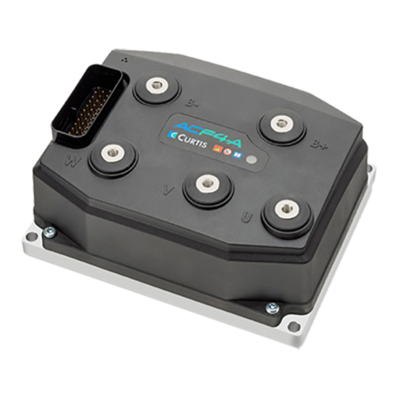
Curtis AC F4-A Motor Controller – August 2020 Return to TOC 1 — OVERVIEW The AC F4-A is CAN-based induction-motor controller. Available in either 24 volt or 36-48 volt models, this compact motor controller delivers unmatched performance with a flexible feature set. The Model AC F4-A is fully optimized for use as a traction controller on class III pedestrian-operated powered pallet trucks. -
Page 10: How To Use This Manual
Curtis distributor or the regional Curtis sales-support office for additional technical support. The Curtis sales and support office- contact information is available from the Curtis Instruments website under the International tab. https://www.curtisinstruments.com/international/ pg. -
Page 11: 2: Installation And Wiring
Curtis AC F4-A Motor Controller – August 2020 Return to TOC 2 — INSTALLATION AND WIRING PHYSICALLY MOUNTING THE CONTROLLER Use Figure 2, the F4’s outline and mounting-hole dimensions, to determine the optimum mounting location. Properly installed, the controller meets the IP65 requirements for environmental protection against dust and water. -
Page 12: Precautions
Curtis AC F4-A Motor Controller – August 2020 Return to TOC PRECAUTIONS Take the steps during the application’s design and development to ensure that the EMC performance complies with applicable regulations; Appendix B presents some design considerations for EMC mitigation. Working on electrical systems is potentially dangerous. -
Page 13: Figure 3: Battery Power And Motor Phase Terminal Connections
Curtis AC F4-A Motor Controller – August 2020 Return to TOC The high power connections are aluminum M6 terminals. Terminate the battery and motor cables with high quality (tin-plated) copper lugs to match the application. Ensure the M6 bolts are the proper length to meet the minimum thread depth engagement. -
Page 14: Low Current Connections
Curtis AC F4-A Motor Controller – August 2020 Return to TOC LOW CURRENT CONNECTIONS All logic and low power connections are through a single 35-pin AMPSEAL connector (mold in the cover) utilizing gold-plated pins. The matching AMPSEAL receptacle’s wire silos come sealed by a membrane. -
Page 15: Rotor Position Feedback (Pins 18, 26, 31, 32)
Curtis AC F4-A Motor Controller – August 2020 Return to TOC Figure 5 35-Pin AMPSEAL ISOLATED GROUND NOT USED ON Connection Assignments MODELS w/ Isolated CAN MODELS w/ Isolated CAN INPUT 4 INPUT 31 CAN 1 ENC 1B DRIVER 8 CAN2 H +5V SUPPLY INPUT 9... -
Page 16: All Other Low Power Wiring
Curtis AC F4-A Motor Controller – August 2020 Return to TOC All other low power wiring Use standard vehicle-harness routing practices for the remaining connections. When designing the vehicle’s wiring and routing, keep the inputs such as the throttle, temperature, and the motor feedback signals separate from controller’s output lines such as the coil driver outputs. -
Page 17: Controller Inputs And Outputs
Curtis AC F4-A Motor Controller – August 2020 Return to TOC Controller Inputs and Outputs Table 4 lists the available Inputs and Outputs (I/O) types by the AMPSEAL pin number. Table 4 Logic and Low-Current Connections Special I/O Digital Input Switch Analog Pin Name... -
Page 18: Controller Wiring Diagram (Examples)
Curtis AC F4-A Motor Controller – August 2020 Return to TOC Controller Wiring Diagram (Examples) Figure 6 illustrates the F4-A controller wiring for a Class III pallet truck using wired inputs from switches and potentiometers, driving an induction traction motor. The Interlock, Forward, Reverse, Lift, Lower, and the redundant Emergency Reverse inputs are by external mechanical switches pulled Quick Links: to KSI (B+). -
Page 19: Figure 7: Ac F4-A Can Tiller Head Wiring Diagram
Curtis AC F4-A Motor Controller – August 2020 Return to TOC For CANopen based tiller heads (or similar), see the Figure 7 wiring example. In this CAN-based example, the Interlock, Emergency Reverse, and a Travel Limit are the remaining “wired” switch inputs. -
Page 20: Figure 7A: Ac F4-A Isolated Can
Curtis AC F4-A Motor Controller – August 2020 Return to TOC Interlock Input 5 Emergency Input 9 Coil Supply Reverse Proportional Valve Input 13 / Enc 2B Driver 1 / Input 21 Travel EM Brake Safety Disabled Limit Input 7 Driver 2 / Input 22 Load-Hold Valve Input 8... -
Page 21: Low Current 35-Pin Connector Electrical Specifications
Curtis AC F4-A Motor Controller – August 2020 Return to TOC Low Current 35-pin Connector Electrical Specifications Digital (Switch) Inputs The controller offers flexibility in configuring the digital inputs. For example, when configured as switch inputs, the available inputs easily interface with user switches/buttons for the following: •... - Page 22 Curtis AC F4-A Motor Controller – August 2020 Return to TOC Table 5 Switch (Digital) Inputs Electrical Specifications, cont’d AVAILABLE/ALTERNATIVE SWITCH (DIGITAL) INPUTS (Throttle Wiper, typical usage) > 20k Ω Rising edge = 4 V max Switch 1 Falling edge = 1 V min (Low/Off (pulled to B–) (motor temp sensor, typical usage) Based upon usage.
-
Page 23: Analog Inputs
Curtis AC F4-A Motor Controller – August 2020 Return to TOC Analog Inputs The F4-A controller supports a variety of analog inputs. The input’s allowable voltage range varies depending on the primary purpose of the input. Select the analog input that matches the application. Table 6 Analog Inputs Electrical Specifications Input/Signal Name Measurement Range... -
Page 24: Potentiometer Inputs With Dynamic Testing
Curtis AC F4-A Motor Controller – August 2020 Return to TOC Potentiometer Inputs with Dynamic Testing In this manual, the term throttle is for the traction motors. If the vehicle uses a dual drive system, the single throttle input controls both traction motors. Figure 6 illustrates the traction-drive throttle as a traditional 3-wire potentiometer (pot) using pin 16 (Pot 1 Wiper), although Hall-effect voltage throttles are more common today. -
Page 25: Pwm And Digital Drivers
Curtis AC F4-A Motor Controller – August 2020 Return to TOC Table 7 Potentiometer Input/Configuration Electrical Specifications Input Pot Resistance Range Input Output Fault Type Signal Name Available Current Impedance Voltage Detection Pot 6 Supply Pot 1 Wiper 3-Wire Pot Wiper Open 1k –... -
Page 26: Table 8 Driver Outputs Electrical Specifications
Curtis AC F4-A Motor Controller – August 2020 Return to TOC Drivers 6 and 7 are lower-current digital (On/Off) drivers. Use the drivers for dashboard LEDs, piezo-electric buzzers and other low-current switched loads (i.e., high input impedance devices able to accept full coil supply voltage). The F4 controller has two special purpose drivers. -
Page 27: Power Supply Outputs
Curtis AC F4-A Motor Controller – August 2020 Return to TOC Power Supply Outputs The 5-volt and 12-volt power supplies provide auxiliary power for low power circuits such as electronic throttles, displays/gauges, and motor-position feedback devices. The corresponding ground is the controller I/O ground circuit, GND (pins 7 & 18). Typically, the 5-volt supply is for the motor feedback device (encoder or Sin/Cos sensor) as illustrated in the wiring diagrams, Figures 6 and 7. -
Page 28: Keyswitch And Coil Supply
Curtis AC F4-A Motor Controller – August 2020 Return to TOC Keyswitch and Coil Supply Connect the Keyswitch (KSI) input to B+ via a key switch. The keyswitch input (pin 1) feeds the controller’s internal power supplies, the Coil Supply output, and the main-capacitor bank’s precharge (before the main contactor closes). -
Page 29: Can Ports
Curtis AC F4-A Motor Controller – August 2020 Return to TOC CAN Ports Two CAN ports are available. Each CAN port requires a unique Node ID and they can operate at different baud rates. Both isolated CAN and non-isolated CAN port models are available (see Appendix E). On the non-isolated CAN models, both ports share the controller internal power supply and I/O Quick Links: Fig 6... -
Page 30: Motor Position Sensor Inputs
Curtis AC F4-A Motor Controller – August 2020 Return to TOC Motor Position Sensor Inputs The F4-A is designed to control AC induction (ACIM) and (rotor) Surface Permanent Magnet Synchronous Motor (SPMSM) traction motors. To accomplish this, the rotor position inputs accept two types of sensors. -
Page 31: Table 13 Sin/Cos Sensor Device Electrical Specifications
Curtis AC F4-A Motor Controller – August 2020 Return to TOC Use the Sin/Cos sensor in SPMSM (Surface Permanent Magnet Synchronous Motor) applications It is not necessarily applicable to the present F4-A release. Contact Curtis if the F4-A application will use a Sin/Cos sensor. These signal tolerances must be maintained throughout the application’s operating conditions, including voltage, temperature, speed and torque ranges. -
Page 32: Motor Temperature Input
Curtis AC F4-A Motor Controller – August 2020 Return to TOC Motor Temperature Input The traction motor’s temperature sensor input measures the resistance of the connected sensor. The controller supports KTY83, KTY84, and PT1000 temperature sensors. A parameter-VCL sensor configuration profile allows the usage of custom solutions, with a maximum source current of less than 2 mA. -
Page 33: 3: Application-Specific Features
Curtis AC F4-A Motor Controller – August 2020 Return to TOC 3 — APPLICATION-SPECIFIC FEATURES Some of the controller features affect more than the electrical connections or the parameter settings. This chapter provides background information on application-specific features, to assist the vehicle designer in the design and vehicle-development process. -
Page 34: Voltage Limits
Curtis AC F4-A Motor Controller – August 2020 Return to TOC VOLTAGE LIMITS The F-series controllers have both hardware and parameter based voltage limits. During regenerative braking, the system voltage increases as the motor acts like a generator to slow the vehicle. The overvoltage protection cuts back the regenerative braking (regen) to prevent damage to the traction battery and other electrical system components due to the increased voltage once it is above the normal-voltage region. -
Page 35: Over-Voltage Region
Curtis AC F4-A Motor Controller – August 2020 Return to TOC Beyond the default or a redefined normal operating window, the controller’s actions for over- and under-voltage conditions are both voltage and time-duration based. As illustrated in the graph and following paragraphs, these responses are fixed. No parameters can change or modify the hardware restrictions. -
Page 36: Output-Disabled Region
Curtis AC F4-A Motor Controller – August 2020 Return to TOC Output-Disabled Region This is a limited operation region. The output may be disabled and other functions may be disabled. Motor operation is disabled. Displays may turn off and input devices stop working. •... -
Page 37: 4: Programmable Parameters
Curtis AC F4-A Motor Controller – August 2020 Return to TOC 4 — PROGRAMMABLE PARAMETERS PROGRAMMABLE PARAMETERS The AC F4-A controller’s programmable parameters enable the user to customize it to the needs of specific applications. VCL adds the option of changing applicable parameters during operation. To program (change the value) of parameters, a CANbus connection to the CAN1 port is required, using either the Curtis Integrated Toolkit program or the 1313-CANbus model handheld programmer... -
Page 38: Menu Chart Format
References include CiA 301, 303-1, etc. Curtis Integrated The Curtis Integrated Toolkit (CIT) is a Curtis Instruments developed Toolkit software program for configuring and communicating with Curtis Instruments products. Use CIT to program (change and edit parameters, etc.) the Controller. - Page 39 Curtis AC F4-A Motor Controller – August 2020 Return to TOC Object Index The object dictionary is essentially a table that stores configuration and process data. The CANopen standard defines a 16-bit bit index and an 8-bit sub-index. The object dictionary is the method by which CANopen devices communicate.
-
Page 40: Sdo Write Message
Curtis AC F4-A Motor Controller – August 2020 Return to TOC The Curtis Vehicle Control Language (VCL) is an easy to use, powerful programming language that allows developers to customize system functionality for every application. VCL provides flexible CAN communication and I/O configuration. It for customized wiring/setup and easy integration of Curtis instrumentation. - Page 41 Curtis AC F4-A Motor Controller – August 2020 Return to TOC PARAMETER MENU INDEX Table 15 Programmable Parameters Menus: Curtis Integrated Toolkit /1313 HHP CONTROL MODE SELECT..... p. 40 CONTROL MODE SELECT.....p. 40 — Speed Mode Express..p. 40 — Speed Mode......p. 41 — Application Setup....p. 48 —...
-
Page 42: Parameter Menus
Curtis AC F4-A Motor Controller – August 2020 Return to TOC Speed Mode Express Parameter menus Speed Mode Express is a simplified version of Speed Mode with a reduced set of parameters that is adequate for most speed-controlled applications. Speed Mode Express offers a less complex setup when multiple modes are employed (i.e., different maximum speeds, acceleration rates, or braking rates based upon vehicle operating conditions). - Page 43 Curtis AC F4-A Motor Controller – August 2020 Return to TOC Speed Mode Parameter menus Speed Mode offers the most motor response parameters. Note, pertaining to the optional Speed Mode Express parameters within the Speed Mode menus as noted above, always use the VCL parameter name as shown in the Curtis Integrated Toolkit control mode selection.
- Page 44 Curtis AC F4-A Motor Controller – August 2020 Return to TOC EM BRAKE CONTROL......p. 67 BATTERY SETUP........p. 63 INTERLOCK BRAKING......p. 71 ~ EM Brake State — Interlock Brake Enable ~ Keyswitch Voltage — EM Brake Type — Decel Rate HS —...
- Page 45 Curtis AC F4-A Motor Controller – August 2020 Return to TOC VEHICLE ..........p. 80 MAX SPEED SUPERVISION....p. 83 TRAVEL CONTROL SUPERVISION..p. 84 — Metric Units ~ Present Max Speed Limit — Travel Control Supervision Enable — Speed to RPM ~ Max Speed Limit Timer ~ Travel Control Stopped State Timer ~ Vehicle Speed...
- Page 46 Curtis AC F4-A Motor Controller – August 2020 Return to TOC Controller Setup menus CONTROLLER SETUP ....................................p. 85 — INPUTS........................................ p. 86 — PWM Input 10 Type..................................p. 86 Note: The Analog 1 & 6, and 18 & 19 Type parameters are context sensitive based upon the selection as illustrated. —...
- Page 47 Curtis AC F4-A Motor Controller – August 2020 Return to TOC IO ASSIGNMENTS ......p. 100 CURRENT LIMITS ......p. 106 — CHARACTERIZATION TESTS...... p. 112 — CONTROLS......p. 100 — Drive Current Limit — Test Enable — Interlock Input Source —...
-
Page 48: Speed Mode Express
Curtis AC F4-A Motor Controller – August 2020 Return to TOC CONTROL MODE SELECT PARAMETER ALLOWABLE RANGE DEFAULT DESCRIPTION Control Mode Select Enumerated This parameter determines which motor control method will be in effect when controlling the motor: Control_Mode_Select 0 – 1 0 = Speed Mode Express 0x3080 0x00 1 = Speed Mode... -
Page 49: Speed Mode
Curtis AC F4-A Motor Controller – August 2020 Return to TOC SPEED MODE — SPEED CONTROLLER MENU PARAMETER ALLOWABLE RANGE DEFAULT DESCRIPTION Max Speed 100 – 8000 rpm 4000 rpm Defines the maximum requested motor rpm at full throttle. Partially Max_Speed_SpdM applied throttle is scaled proportionately;... - Page 50 Curtis AC F4-A Motor Controller – August 2020 Return to TOC SPEED MODE/SPEED CONTROLLER — ACC FEEDFORWARD MENU PARAMETER ALLOWABLE RANGE DEFAULT DESCRIPTION Kaff 0 – 500A 0 Amp The design of the acceleration feedforward term is to improve Kaff_SpdM throttle responsiveness and speed controller performance at 0 –...
- Page 51 Curtis AC F4-A Motor Controller – August 2020 Return to TOC SPEED MODE — RESPONSE MENU PARAMETER ALLOWABLE RANGE DEFAULT DESCRIPTION Full Accel Rate HS 0.1 – 30.0 s 5.0 sec Sets the rate (in seconds/Typical Max Speed) at which the speed Full_Accel_Rate_HS_SpdM command increases when applying full throttle at high vehicle 100 –...
-
Page 52: Figure 8: Acceleration Rate Response
Curtis AC F4-A Motor Controller – August 2020 Return to TOC SPEED MODE/RESPONSE — FINE TUNING MENU PARAMETER ALLOWABLE RANGE DEFAULT DESCRIPTION HS (High Speed) 0 – 100 % 70 % Sets the percentage of the Typical Max Speed above which the HS parameters will be used. -
Page 53: Figure 9: Braking Response Rate
Curtis AC F4-A Motor Controller – August 2020 Return to TOC Figure 9 Braking Response Rate FASTER BRAKE RATE Braking Response Rate (seconds) Diagram. In this example, Full Brake Rate HS = 1.5 100% Brake HS = 70 %, Full Brake Rate LS = 3.0 LS = 30 %, Typical Max Speed = 5000 rpm Low Brake Rate = 20.0... - Page 54 Curtis AC F4-A Motor Controller – August 2020 Return to TOC SPEED MODE/RESTRAINT — POSITION HOLD MENU PARAMETER ALLOWABLE RANGE DEFAULT DESCRIPTION Position Hold Enable Off [PCF] On/Off Allows entering the Position Hold mode at zero throttle when the Position_Hold_Enable vehicle comes to a stop.
- Page 55 Curtis AC F4-A Motor Controller – August 2020 Return to TOC SPEED MODE/RESTRAINT — POSITION HOLD MENU , cont’d PARAMETER ALLOWABLE RANGE DEFAULT DESCRIPTION Exit Rollback Reduction 0 – 100 % 50 % This function is applicable when the Torque Preload Enable Exit_Rollback_Reduction function has been Disabled (Off) or the Torque Preload Cancel 0 –...
-
Page 56: Application Setup
Curtis AC F4-A Motor Controller – August 2020 Return to TOC APPLICATION SETUP — THROTTLE MENU PARAMETER ALLOWABLE RANGE DEFAULT DESCRIPTION Throttle Input 0.0 – 100.0 % Read Only Normalized percentage of the throttle input (pin 16 basis). Throttle_Pot_Percent 0 – 1000 Note, this monitor variable appears in the System Monitor »... - Page 57 Curtis AC F4-A Motor Controller – August 2020 Return to TOC APPLICATION SETUP — THROTTLE MENU , cont’d PARAMETER ALLOWABLE RANGE DEFAULT DESCRIPTION Reverse Map Shape 0 – 100 % 35 % The same as the Forward Map Shape parameter counterpart and Reverse_Map applies when throttle direction is reversed (negative motor rpm).
-
Page 58: Figure 10 Throttle Adjustments Diagram
Curtis AC F4-A Motor Controller – August 2020 Return to TOC Figure 10 Max Input parameter Throttle Adjustments adjusts this endpoint. Diagram The effect of throttle Map Shape parameter determines the “knee” in the output; this knee is adjustment parameters. at an 80% Map Shape setting. - Page 59 Curtis AC F4-A Motor Controller – August 2020 Return to TOC throttle, the signal-voltage is also converted to a percentage (Percent, see the Inputs menu) and then processed in VCL. In these cases, the variable VCL_Throttle_Pot is used to process throttle signals –...
-
Page 60: Figure 11: Throttle Signal Processing
Curtis AC F4-A Motor Controller – August 2020 Return to TOC pg. 52 4 — PROGRAMMABLE PARAMETERS... - Page 61 Curtis AC F4-A Motor Controller – August 2020 Return to TOC APPLICATION SETUP — BRAKE MENU PARAMETER ALLOWABLE RANGE DEFAULT DESCRIPTION Brake Input 0.0 – 100.0 % Read Only Normalized percentage of the brake input. Similarly to the Throttle Brake_Pot_Percent Input variable, the controller processes the voltage at the assigned 0 –...
- Page 62 Curtis AC F4-A Motor Controller – August 2020 Return to TOC Figure 12 illustrates the Brake’s signal chain where the brake parameters are applied. Brake processing is optional as it can be turned off by setting Brake_Pedal_Enable = Off. When turned on, note that the brake processing can be with or without VCL.
-
Page 63: Figure 12: Brake Signal Processing
Curtis AC F4-A Motor Controller – August 2020 Return to TOC Brake_Command Mapped_Brake Brake_Pot_Percent Brake Source Brake Max Input Brake Min Input Brake Offset Brake Map Shape VCL_Brake_Pot Pin No. Analog1 VCL_Brake Analog6 100% Forward Analog18 Brake Input Analog19 VCL_Brake_Enable= On Reverse IO Assignments / Controls Menu... - Page 64 Curtis AC F4-A Motor Controller – August 2020 Return to TOC APPLICATION SETUP — CAN INTERFACE MENU PARAMETER ALLOWABLE RANGE DEFAULT DESCRIPTION CANopen Interlock On/Off When programmed On CAN NMT State must = 5 (operational CANopen_Interlock_Enable state) in order for the interlock to be set. On/Off 0x34B4 0x00 Baud Rate...
- Page 65 Curtis AC F4-A Motor Controller – August 2020 Return to TOC Isolated CAN models CAN1 and CAN2 do not have internal 120Ω termination. Pin 34 is the CAN-circuit isolated (reference) ground. Do not use the controller’s I/O ground (pins 7 and 18) for the isolated CAN connections.
- Page 66 Curtis AC F4-A Motor Controller – August 2020 Return to TOC APPLICATION SETUP/CAN INTERFACE — PDO SETUPS MENU PARAMETER ALLOWABLE RANGE DEFAULT DESCRIPTION RPDO1 Note: PDO transmissions are from the perspective of the ancillary controller RPDOs are messages received by the ancillary (i.e., send from the manager) Timeout 0 –...
- Page 67 Curtis AC F4-A Motor Controller – August 2020 Return to TOC APPLICATION SETUP/CAN INTERFACE — PDO SETUPS MENU , cont’d PARAMETER ALLOWABLE RANGE DEFAULT DESCRIPTION TPDO1 Note: PDO transmissions are from the perspective of the ancillary controller TPDOs are messages transmitted from the ancillary (i.e., send to the manager) Event Time 0 –...
- Page 68 Curtis AC F4-A Motor Controller – August 2020 Return to TOC APPLICATION SETUP — CAN INTERFACE 2 MENU CAN2: The second CAN port operates with a different parameter value when the matching parameter has a different CAN Object Index. When the CAN Object is the same, set both CAN1 and CAN2 parameters at the same value.
- Page 69 Curtis AC F4-A Motor Controller – August 2020 Return to TOC APPLICATION SETUP/CAN INTERFACE 2 — PDO SETUPS MENU PARAMETER ALLOWABLE RANGE DEFAULT DESCRIPTION RPDO1 (CAN2) Note: PDO transmissions are from the perspective of the ancillary controller RPDOs are messages received by the ancillary (i.e., send from the manager) Timeout 0 –...
- Page 70 Curtis AC F4-A Motor Controller – August 2020 Return to TOC APPLICATION SETUP/CAN INTERFACE 2 — PDO SETUPS MENU , cont’d PARAMETER ALLOWABLE RANGE DEFAULT DESCRIPTION TPDO1 (CAN2) Note: PDO transmissions are from the perspective of the ancillary controller TPDOs are messages transmitted from the ancillary (i.e., send to the manager) Timeout 0 –...
- Page 71 Curtis AC F4-A Motor Controller – August 2020 Return to TOC APPLICATION SETUP — BATTERY SETUP MENU PARAMETER ALLOWABLE RANGE DEFAULT DESCRIPTION Keyswitch Voltage 0.00 – 105.00 V Read Only Voltage at KSI (pin 1) Keyswitch_Voltage 0 – 10500 0x3398 0x00 Nominal Voltage 24.0 –...
- Page 72 Curtis AC F4-A Motor Controller – August 2020 Return to TOC APPLICATION SETUP/BATTERY SETUP — OVER VOLTAGE CONTROLLER MENU PARAMETER ALLOWABLE RANGE DEFAULT DESCRIPTION User Overvoltage 105 – 200 % 125 % The value of this parameter is a percentage of the Nominal User_Overvoltage Voltage setting.
- Page 73 Curtis AC F4-A Motor Controller – August 2020 Return to TOC APPLICATION SETUP — MAIN CONTACTOR MENU PARAMETER ALLOWABLE RANGE DEFAULT DESCRIPTION Main Enable On/Off When programmed On the controller's native software Main_Enable controls the main contactor when enabling the interlock. When On/Off programmed Off, VCL controls the main contactor.
- Page 74 Curtis AC F4-A Motor Controller – August 2020 Return to TOC APPLICATION SETUP — MAIN CONTACTOR MENU , cont’d PARAMETER ALLOWABLE RANGE DEFAULT DESCRIPTION Open Delay 0.0 – 40.0 s 0.1 sec Applicable only when Interlock Type = 0 or 1. The delay can be Open_Delay set to allow the contactor to remain closed for a period of time 0 –...
- Page 75 Curtis AC F4-A Motor Controller – August 2020 Return to TOC APPLICATION SETUP — EM BRAKE CONTROL MENU PARAMETER ALLOWABLE RANGE DEFAULT DESCRIPTION EM Brake State 0 – 4 Read Only EM Brake State: EMBrakeState 0 – 4 0 = engaged 0x347A 0x00 1 = releasing 2 = released...
- Page 76 Curtis AC F4-A Motor Controller – August 2020 Return to TOC APPLICATION SETUP — EM BRAKE CONTROL MENU , cont’d PARAMETER ALLOWABLE RANGE DEFAULT DESCRIPTION Set EM Brake On Fault On/Off When programmed On, the controller’s operating system will EM_Brake_Set_Upon_Fault stop the assigned EM Brake's coil driver whenever a fault occurs On/Off that has the ShutdownEMBrake fault action.
- Page 77 Curtis AC F4-A Motor Controller – August 2020 Return to TOC APPLICATION SETUP — EM BRAKE CONTROL MENU , cont’d PARAMETER ALLOWABLE RANGE DEFAULT DESCRIPTION Save Torque Preload On/Off Enabling this parameter will save the Torque preload Save_Torque_Preload (HillHoldMemory) across keyswitch cycles. If Torque_Preload_ On/Off Cancel_Delay is nonzero and this parameter = On, the timer starts 0x3474 0x00...
-
Page 78: Figure 13: Emergency Reverse Supervision Function
Curtis AC F4-A Motor Controller – August 2020 Return to TOC APPLICATION SETUP/EMERGENCY REVERSE (EMR) — EMR SUPERVISION MENU PARAMETER ALLOWABLE RANGE DEFAULT DESCRIPTION Supervision Enable On/Off Enables or disables the EMR supervision function. EMR_Supervision_Enable On/Off On = EMR supervision is enabled. 0x34A4 0x00 Off = EMR supervision is disabled. - Page 79 Curtis AC F4-A Motor Controller – August 2020 Return to TOC APPLICATION SETUP — INTERLOCK BRAKING MENU PARAMETER ALLOWABLE RANGE DEFAULT DESCRIPTION Interlock Brake Enable On/Off Determines whether the interlock braking function is active. Interlock_Brake_Enable On/Off On = The controller will attempt to bring the vehicle to a stop using regen braking when the interlock signal is removed.
-
Page 80: Figure 14: Interlock Brake Supervision Speed Limit For Positive Initial Speed
Curtis AC F4-A Motor Controller – August 2020 Return to TOC APPLICATION SETUP/INTERLOCK BRAKING — INTERLOCK BRAKING SUPERVISION MENU PARAMETER ALLOWABLE RANGE DEFAULT DESCRIPTION Tolerance 0 – 1000 rpm 500 rpm The motor speed must exceed this value plus the window Interlock_Brake_Supervision_ defined by the entry speed, ramp rate, and zero speed. -
Page 81: Figure 15: Interlock Brake Supervision Speed Limit For Negative Initial Speed
Curtis AC F4-A Motor Controller – August 2020 Return to TOC Figure 15 Interlock Brake Supervision Speed Limit for Negative Initial Speed Figure 16 Interlock Brake Supervision Distance Check 4 — PROGRAMMABLE PARAMETERS pg. 73... - Page 82 Curtis AC F4-A Motor Controller – August 2020 Return to TOC Hydraulic Pump Motor, Load-Hold and Proportional Valves See the Controller Setup/IO Assignments/Controls menu. See a pump-combi controller manual, e.g., 53228_AC F2-C_RevA (or newer) APPLICATION SETUP/HYDRAULICS — LIFT SETTINGS MENU The parameters in this menu, for this non-combi controller, do not offer “throttling”...
- Page 83 Curtis AC F4-A Motor Controller – August 2020 Return to TOC This is a Proportional hydraulic lift/lower system. It allows for a variable-rate lower through the use of a proportional valve (PV). - The speed of the DC pump motor regulates how quickly the hydraulic fluid can push up the Lift cylinder.
-
Page 84: Figure 18: Hydraulic System Diagram, With A Fixed (On/Off) Load-Hold Valve
Curtis AC F4-A Motor Controller – August 2020 Return to TOC This is a fixed (On/Off) hydraulic Lift/Lower System. A Proportional (variable rate) lowering valve is not used. The Load Hold Valve (LHV) is used as the lowering valve. During Lift, the DC pump motor drives the hydraulic pump, which forces hydraulic fluid up the hoses and into the Lift cylinder. -
Page 85: Figure 19: Lift-Input Signal Chain (Processing)
Curtis AC F4-A Motor Controller – August 2020 Return to TOC Lift-Input Processing Lift Input(s) Function Configuration Parameter Run-time Variable VCL Function/Variable Lift_Map Lift_Offset Lift_Max_Percent Lift_Pot_Percent Lift_BDI_Lockout Lift_Deadband_Percent Mapped_Lift_Throttle Lift_Input_Type Lift_Input_Source VCL_Throttle_Enable > 0 VCL_Lift_Throttle_Pot Pin# Type Hydraulic_Lower_Throttle > 0% Input1 / Analog1 Limit Stop Checks for Battery Discharge Indicator low battery... - Page 86 Curtis AC F4-A Motor Controller – August 2020 Return to TOC APPLICATION SETUP/HYDRAULICS — LIFT SETTINGS MENU PARAMETER ALLOWABLE RANGE DEFAULT DESCRIPTION Lift Input 0.0 – 100.0 % Read Only Lift pot input after source selection and before mapping as a Lift_Pot_Percent percentage.
- Page 87 Curtis AC F4-A Motor Controller – August 2020 Return to TOC APPLICATION SETUP/HYDRAULICS — LOWER SETTINGS MENU PARAMETER ALLOWABLE RANGE DEFAULT DESCRIPTION Lower Input 0.0 – 100.0 % Read Only Lower pot input after source selection and before mapping as a Lower_Pot_Percent percentage.
- Page 88 Curtis AC F4-A Motor Controller – August 2020 Return to TOC DUAL DRIVE See the Dual Drive Supplement manual: 53231_F-Series Dual Drive RevA (or newer). APPLICATION SETUP — VEHICLE MENU PARAMETER ALLOWABLE RANGE DEFAULT DESCRIPTION Metric Units Off / On Off (0) When this parameter is On, the distance variables (Vehicle Metric_Units...
- Page 89 Curtis AC F4-A Motor Controller – August 2020 Return to TOC APPLICATION SETUP/VEHICLE — SPEED/DIST/ACCEL MENU PARAMETER ALLOWABLE RANGE DEFAULT DESCRIPTION Capture Speed 1 0 – 8000 rpm 4500 The controller captures the time it takes the motor to go from 0 Capture_Speed_1 rpm to the programmed Capture Speed.
- Page 90 Curtis AC F4-A Motor Controller – August 2020 Return to TOC APPLICATION SETUP/VEHICLE — SPEED/DIST/ACCEL MENU , cont’d PARAMETER ALLOWABLE RANGE DEFAULT DESCRIPTION Time Between Speeds 0.00 – 128.00 s Read Only Time taken for the vehicle to go from programmed Capture Speed Time_Between_Capture_Speeds 1 to programmed Capture Speed 2 during its most recent such 0 –...
- Page 91 Curtis AC F4-A Motor Controller – August 2020 Return to TOC APPLICATION SETUP — MAX SPEED SUPERVISION MENU PARAMETER ALLOWABLE RANGE DEFAULT DESCRIPTION Present Max Speed Limit –2147483648 – Read Only A monitor variable, in rpm, that shows the present (real time) Max Current_Max_Speed_Limit 2147483647 Speed Limit accounting for the Max Speed Limit percent and Max...
- Page 92 Curtis AC F4-A Motor Controller – August 2020 Return to TOC APPLICATION SETUP — TRAVEL CONTROL SUPERVISION MENU PARAMETER ALLOWABLE RANGE DEFAULT DESCRIPTION Travel Control Supervision On/Off Enables Travel Control checking. Travel Control is a safety Enable function that checks that the vehicle is not started from a stopped On/Off Travel_Control_Fault_Enable state (at rest) on level ground unless the controls for speed and...
-
Page 93: Controller Setup
Curtis AC F4-A Motor Controller – August 2020 Return to TOC CONTROLLER SETUP Use the menus within the Controller Setup to configure the controller’s inputs and output signals at the low-voltage (35-pin connector) and the current and power at the UVW motor-phase and Battery connections. - Page 94 Curtis AC F4-A Motor Controller – August 2020 Return to TOC CONTROLLER SETUP — INPUTS MENU PARAMETER ALLOWABLE RANGE DEFAULT DESCRIPTION PWM Input 10 Type 0 – 2 Input 10 (pin 10) is a high frequency input for either duty-cycle PWM_Input_10_Type or frequency signals.
-
Page 95: Figure 21: Input 10 Digital And Analog Signal Chain
Curtis AC F4-A Motor Controller – August 2020 Return to TOC Default=16ms Switches[] Switch Debounce PWM_Input_10_Duty_Cycle PWM_Input_10_Low_Duty_Cycle PWM_Input_10_High_Duty_Cycle 100% Input_10 Duty Cycle DC scaling to min/max range Measurement If any PWM Faults Active NONE PWM_Input_10_Frequency PWM_Input_10_Percent PWM_Input_10_Low_Frequency PWM_Input_10_High_Frequency f=1/T PWM_Input_10_Type 100% Frequency Measurement... - Page 96 Curtis AC F4-A Motor Controller – August 2020 Return to TOC CONTROLLER SETUP — INPUTS MENU, cont’d PARAMETER ALLOWABLE RANGE DEFAULT DESCRIPTION 0.0 – 11.0 V 0.0 V The minimum input voltage before a fault is declared. When the Analog_Input_1_Low Analog 1 Type selection is voltage, this set point represents the 0 –...
- Page 97 Curtis AC F4-A Motor Controller – August 2020 Return to TOC CONTROLLER SETUP — INPUTS MENU, cont’d PARAMETER ALLOWABLE RANGE DEFAULT DESCRIPTION Analog 1 menu Parameters for Voltage with Supply selection Analog 1 Type Voltage with Supply – The Analog 1 Type “Voltage with Supply” selection operates the Analog_Input_1_Type Analog 1 input (pin 16) as a raw voltage input with an internal (selection menu)
- Page 98 Curtis AC F4-A Motor Controller – August 2020 Return to TOC CONTROLLER SETUP — INPUTS MENU, cont’d PARAMETER ALLOWABLE RANGE DEFAULT DESCRIPTION 0.0 – 7.0 V 0.0 V The minimum input voltage before a fault is declared. Analog_Input_2_Low 0 – 700 This voltage represents the 0% point for the normalized inputs.
- Page 99 Curtis AC F4-A Motor Controller – August 2020 Return to TOC CONTROLLER SETUP — INPUTS MENU, cont’d PARAMETER ALLOWABLE RANGE DEFAULT DESCRIPTION High 0.0 – 30.0 V 30.0 V The maximum input voltage before a fault is declared. Analog_Input_5_High 0 – 3000 This voltage is the 100 % point for the normalized inputs.
- Page 100 Curtis AC F4-A Motor Controller – August 2020 Return to TOC CONTROLLER SETUP — INPUTS MENU, cont’d PARAMETER ALLOWABLE RANGE DEFAULT DESCRIPTION Nominal Resistance 800 – 15000 Ohms 5000 Ω Set the potentiometer resistance. Pot_6_R Throttle or Brake potentiometers are typically 1k, 5k, or 10k Ohms. 0x336C 0x00 Note: If this parameter value is outside the actual resistance, it will trigger a Throttle Input fault (Flash code 0x42) if Throttle_...
- Page 101 Curtis AC F4-A Motor Controller – August 2020 Return to TOC CONTROLLER SETUP — INPUTS MENU, cont’d PARAMETER ALLOWABLE RANGE DEFAULT DESCRIPTION 0.0 – 11.0 V 0.0 V The minimum input voltage before a fault is declared. When the Analog_Input_6_Low Analog 6 Type selection is Voltage with Supply, this set point 0 –...
- Page 102 Curtis AC F4-A Motor Controller – August 2020 Return to TOC CONTROLLER SETUP — INPUTS MENU, cont’d PARAMETER ALLOWABLE RANGE DEFAULT DESCRIPTION High 0.0 – 30.0 V 30.0 V The maximum input voltage before a fault is declared. Analog_Input_8_High 0 – 3000 This voltage is the 100% point for the normalized inputs.
- Page 103 Curtis AC F4-A Motor Controller – August 2020 Return to TOC CONTROLLER SETUP — INPUTS MENU, cont’d PARAMETER ALLOWABLE RANGE DEFAULT DESCRIPTION Percent 0.0 – 100.0 % Read Only The percentage of the voltage at pin 17 based upon the Analog_Input_Percent_18 0 –...
- Page 104 Curtis AC F4-A Motor Controller – August 2020 Return to TOC CONTROLLER SETUP — INPUTS MENU, cont’d PARAMETER ALLOWABLE RANGE DEFAULT DESCRIPTION Nominal Resistance 800 – 15000 Ω 5000 Ω Set the nominal resistance of the potentiometer. Pot_18_R 800 – 15000 Throttle or Brake potentiometers are typically 1k, 5k, or 10k Ohms.
- Page 105 Curtis AC F4-A Motor Controller – August 2020 Return to TOC CONTROLLER SETUP — INPUTS MENU, cont’d PARAMETER ALLOWABLE RANGE DEFAULT DESCRIPTION Analog 19 menu Analog 19 Type Enumeration Voltage Configure the Analog 19 input by throttle or load type. Analog_Input_19_Type 0 –...
- Page 106 Curtis AC F4-A Motor Controller – August 2020 Return to TOC CONTROLLER SETUP — INPUTS MENU, cont’d PARAMETER ALLOWABLE RANGE DEFAULT DESCRIPTION Nominal Resistance 800 – 15000 Ohms 5000 Ω Set the potentiometer resistance. Pot_19_R Throttle or Brake potentiometers are typically 1k, 5k, or 10k Ohms. 0x336D 0x00 Note: If this parameter value is outside the actual resistance, it will trigger a Throttle Input fault (Flash code 0x42) if Throttle_...
- Page 107 Curtis AC F4-A Motor Controller – August 2020 Return to TOC CONTROLLER SETUP — INPUTS MENU, cont’d PARAMETER ALLOWABLE RANGE DEFAULT DESCRIPTION 0.0 – 11.0 V 0.0 V The minimum input voltage before a fault is declared. When the Analog_Input_19_Low Analog 18 Type selection is Voltage with Supply, this set point 0 –...
- Page 108 Curtis AC F4-A Motor Controller – August 2020 Return to TOC CONTROLLER SETUP/IO ASSIGNMENTS — CONTROLS MENU PARAMETER ALLOWABLE RANGE DEFAULT DESCRIPTION Interlock Input Source 0 – 32 Interlock switch assignment. Interlock_Input_Source 0 – 32 [PCF] Using the available switch inputs, select the digital input number that the interlock will use.
- Page 109 Curtis AC F4-A Motor Controller – August 2020 Return to TOC CONTROLLER SETUP/IO ASSIGNMENTS — CONTROLS MENU, cont’d PARAMETER ALLOWABLE RANGE DEFAULT DESCRIPTION Hydraulics Inhibit Type 0 – 3 Prevents accidental turn-on of peripherals at startup/key-cycle. Hydraulics_Inhibit_Type 0 – 3 0 - No inhibit 0x3702 0x00 1 - Lift Only...
- Page 110 Curtis AC F4-A Motor Controller – August 2020 Return to TOC CONTROLLER SETUP/IO ASSIGNMENTS — SWITCH STATUS MENU The read only switch inputs On/Off status include the inputs on any pins that can process a voltage reading. Use the on/off status in this menu during setup and application development to verify an “input”...
- Page 111 Curtis AC F4-A Motor Controller – August 2020 Return to TOC CONTROLLER SETUP/IO ASSIGNMENTS — SWITCH STATUS MENU, cont’d DESCRIPTION PARAMETER ALLOWABLE RANGE DEFAULT MONITORS THE CONTROLLER SWITCH STATUS Switch 18 On/Off Read Only Pin 17 Switch_18 On/Off 0x333D 0x00 Switch 19 On/Off Read Only...
- Page 112 Curtis AC F4-A Motor Controller – August 2020 Return to TOC CONTROLLER SETUP/IO ASSIGNMENTS — COIL DRIVERS MENU These are the standard coil-driver assignments using Drivers 1-5. A selection of “0” indicates no driver is assigned. Note that the EM Brake driver, as shown in Fig 6 and 7 is a 3-amp driver. The other PWM drivers are 2 amperes.
- Page 113 Curtis AC F4-A Motor Controller – August 2020 Return to TOC CONTROLLER SETUP — OUTPUTS MENU, cont’d PARAMETER ALLOWABLE RANGE DEFAULT DESCRIPTION Driver 2–7 Driver X Checks Enable On/Off See Driver 1 Driver_X_Checks On/Off X = 2–7. Driver_2_Checks : 0x341C 0x00 Driver_3_Checks : 0x341D 0x00 Driver_4_Checks : 0x341E 0x00 Driver_5_Checks : 0x341F 0x00...
- Page 114 Curtis AC F4-A Motor Controller – August 2020 Return to TOC CONTROLLER SETUP — CURRENT LIMITS MENU PARAMETER ALLOWABLE RANGE DEFAULT DESCRIPTION Drive Current Limit 0 – 100 % 100 % Sets the maximum RMS current the controller will supply to the Drive_Current_Limit motor during drive operation as a percentage of the controller's 0 –...
-
Page 115: Figure 22: Drive Current Limiting Map
Curtis AC F4-A Motor Controller – August 2020 Return to TOC CONTROLLER SETUP/CURRENT LIMITS/POWER LIMITS — DRIVE LIMITING MAP MENU PARAMETER ALLOWABLE RANGE DEFAULT DESCRIPTION Nominal 0 – 100 % 100 % These parameters define the percentage of the applied drive PL_Drive_Nominal current limit at the speeds defined by the nominal speed and 0 –... -
Page 116: Figure 23: Regen Current Limiting Map
Curtis AC F4-A Motor Controller – August 2020 Return to TOC CONTROLLER SETUP/CURRENT LIMITS/POWER LIMITS — REGEN LIMITING MAP MENU PARAMETER ALLOWABLE RANGE DEFAULT DESCRIPTION Nominal 0 – 100 % 100 % These parameters define the percentage of the applied regen PL_Regen_Nominal current limit or braking current limit at the speeds defined by the 0 –... -
Page 117: Ac Motor Setup Menu
Max Speed parameters. 0 – 12000 8000* RPM 0x30AF 0x00 *For speeds over 8000 rpm, consult Curtis Instruments. Typical Max Speed 500 – 8000 rpm 4000 rpm Set this parameter to the typical maximum motor speed of the Typical_Max_Speed vehicle. - Page 118 Curtis AC F4-A Motor Controller – August 2020 Return to TOC AC MOTOR SETUP — INDUCTION MOTOR (ACIM) MENU PARAMETER ALLOWABLE RANGE DEFAULT DESCRIPTION Swap Two Phases On/Off If after Swap Encoder Direction has been set correctly the vehicle Swap_Two_Phases drives in the wrong direction (i.e.
- Page 119 Curtis AC F4-A Motor Controller – August 2020 Return to TOC AC MOTOR SETUP/INDUCTION MOTOR (ACIM) — FIELD WEAKENING MENU, cont’d PARAMETER ALLOWABLE RANGE DEFAULT DESCRIPTION Test Field Current 0.0 – 800.0 A Read Only Use this reading during the ACIM motor characterization Test_Field_Current procedure.
- Page 120 Curtis AC F4-A Motor Controller – August 2020 Return to TOC AC MOTOR SETUP/INDUCTION MOTOR (ACIM) — LIMITED OPERATING STRATEGY MENU PARAMETER ALLOWABLE RANGE DEFAULT DESCRIPTION LOS Upon Encoder Fault On/Off The Limited Operating Strategy (LOS) is typically to drive the LOS_Upon_Encoder_Fault vehicle back to a repair center at very low speeds in the event the On/Off...
- Page 121 Curtis AC F4-A Motor Controller – August 2020 Return to TOC AC MOTOR SETUP/INDUCTION MOTOR (ACIM) — CHARACTERIZATION TESTS MENU, cont’d PARAMETER ALLOWABLE RANGE DEFAULT DESCRIPTION Motor Poles 2 – 8 The number of motor pole pairs. IM_Motor_Poles 1 – 4 [PCF] This parameter selects the number of poles before beginning the 0x4F5D 0x00...
- Page 122 Curtis AC F4-A Motor Controller – August 2020 Return to TOC AC MOTOR SETUP — QUADRATURE ENCODER MENU PARAMETER ALLOWABLE RANGE DEFAULT DESCRIPTION 5V Output Enable On/Off Enables the 5V Power Supply Output. Ext_5V_Output_Enable On/Off 0x36A8 0x00 12V Output Enable On/Off Enables the 12V Power Supply Output.
- Page 123 Curtis AC F4-A Motor Controller – August 2020 Return to TOC AC MOTOR SETUP — TEMPERATURE SENSOR MENU PARAMETER ALLOWABLE RANGE DEFAULT DESCRIPTION Sensor Enable On/Off When programmed On, this parameter enables both the motor MotorTemp_Sensor_Enable temperature cutback and the motor temperature compensation On/Off features.
-
Page 124: 5: System Monitor
Curtis AC F4-A Motor Controller – August 2020 Return to TOC 5 — SYSTEM MONITOR MENU Table 16 System Monitor Variables INPUTS MENU......p. 117 CONTROLLER MENU....MOTOR MENU......p. 124 p. 122 — Throttle Input — Motor RPM — Current (RMS) —... - Page 125 Curtis AC F4-A Motor Controller – August 2020 Return to TOC SYSTEM MONITOR MENU: INPUTS VARIABLE DISPLAY RANGE DESCRIPTION Throttle Input 0.0 – 100.0 % The percent of maximum voltage at the pot wiper (pin 16). Throttle_Pot_Percent 0 – 1000 0x3360 0x00 Mapped Throttle –100.0 –...
- Page 126 Curtis AC F4-A Motor Controller – August 2020 Return to TOC SYSTEM MONITOR / INPUTS MENU: SWITCH STATUS VARIABLE DISPLAY RANGE DESCRIPTION Switch 1 On/Off Switch 1 On or Off (pin 16). Switch_1 On/Off Note: Typically used as the 3-wire throttle Pot Wiper input. 0x3324 0x00 Switch 2 On/Off...
- Page 127 Curtis AC F4-A Motor Controller – August 2020 Return to TOC SYSTEM MONITOR / INPUTS MENU: SWITCH STATUS, cont’d VARIABLE DISPLAY RANGE DESCRIPTION Switch 21 On/Off Switch 21 On or Off (pin 2). Switch_21 On/Off Note: Typically not configured as a switch, but as Driver1. 0x3332 0x00 Switch 22 On/Off...
- Page 128 Curtis AC F4-A Motor Controller – August 2020 Return to TOC SYSTEM MONITOR / INPUTS MENU: ANALOG INPUTS VARIABLE DISPLAY RANGE DESCRIPTION Analog 1 –327.68 – 327.67 V Voltage at analog 1 (pin 16). analog_input_volts_1 –32768 – 32767 0x3B2E 0x00 Analog 2 –327.68 –...
- Page 129 Curtis AC F4-A Motor Controller – August 2020 Return to TOC SYSTEM MONITOR MENU: OUTPUTS VARIABLE DISPLAY RANGE DESCRIPTION Driver 1 PWM 0.000 – 100.000 % Driver 1 PWM output percentage (pin 2). Driver_1_PWM 0 – 32767 0x3402 0x00 Driver 2 PWM 0.000 –...
- Page 130 Curtis AC F4-A Motor Controller – August 2020 Return to TOC SYSTEM MONITOR MENU: CONTROLLER VARIABLE DISPLAY RANGE DESCRIPTION Current (RMS) 0.0 – 1000.0 A The RMS current of the controller, taking all three phases into account. Current_RMS 0 – 10000 0x3082 0x00 Modulation Depth 0.0 –...
- Page 131 Curtis AC F4-A Motor Controller – August 2020 Return to TOC SYSTEM MONITOR MENU: CUTBACKS VARIABLE DISPLAY RANGE DESCRIPTION Motor Temperature Cutback 0.00 – 100.00 % Displays the current available resulting from the motor temperature cutback MotorTempCutback function. A value of 100% indicates no cutback in current. 0 –...
- Page 132 Curtis AC F4-A Motor Controller – August 2020 Return to TOC SYSTEM MONITOR MENU: MOTOR MENU VARIABLE DISPLAY RANGE DESCRIPTION Motor RPM –32768 – 32767 rpm Motor speed in revolutions per minute (rpm). Motor_RPM –32768 – 32767 0x352F 0x00 Temperature –100.0 –...
- Page 133 Curtis AC F4-A Motor Controller – August 2020 Return to TOC SYSTEM MONITOR MENU: VEHICLE MENU VARIABLE DISPLAY RANGE DESCRIPTION Vehicle Speed –3276.8 – 3276.7 Vehicle speed in units of MPH or KPH depending on the setting of the Metric Vehicle_Speed Units parameter.
- Page 134 Curtis AC F4-A Motor Controller – August 2020 Return to TOC MONITOR MENU: VEHICLE, cont’d VARIABLE DISPLAY RANGE DESCRIPTION Distance Since Stop 0.0 – 1000000.0 Distance traveled by the vehicle starting from a stop. In effect, this Distance_Since_Stop parameter uses the vehicle as a tape measure. 0 –...
-
Page 135: 6: Commissioning
Curtis AC F4-A Motor Controller – August 2020 Return to TOC 6 — COMMISSIONING INITIAL SETUP The F-Series controllers are suitable for a variety of vehicles that differ widely in characteristics. Consequently, not all parameters or control modes may be appropriate to a given application, nor are the default parameter values. -
Page 136: To Begin
Curtis AC F4-A Motor Controller – August 2020 Return to TOC ACIM: If Curtis has provided the values for Motor Type, FW Base Speed, and Field Weakening Drive, these will be set on the controller prior to fine-tuning the motor. If using the automated motor characterization procedure, the FW Base Speed, and Field Weakening Drive are set following the auto-characterization and prior to completing the fine-tuning. -
Page 137: Ac Traction Motor Setup Guide
Curtis AC F4-A Motor Controller – August 2020 Return to TOC Application Setup menu parameters, Speed Mode/Speed Mode Express parameters. Use the following steps as a guide to the minimum parameter selections. These steps follow the generic/ default wiring diagram (Figure 6) for selectable induction motor types, unless noted otherwise. Be aware that some parameters may appear in multiple menus, so setting such parameters in a given menu will change it in the other. - Page 138 Curtis AC F4-A Motor Controller – August 2020 Return to TOC If the motor temperature is not correct, double-check the motor temperature control parameters Sensor Enable, Sensor Type, and Sensor Offset. Ensure that the thermistor wiring orientation has its negative (ground) side connected ground input (e.g., pin 18). To setup a custom sensor type, set Type = Custom (Type 0- Custom).
-
Page 139: Controller Setup Guide
Curtis AC F4-A Motor Controller – August 2020 Return to TOC Encoder Fault Setup. See Programmer » AC Motor Setup » Quadrature Encoder » Encoder Fault Setup » menu. The parameters’ default values within this menu are typically sufficient for operation. The Fault Detection Enable should be On. - Page 140 Curtis AC F4-A Motor Controller – August 2020 Return to TOC Step 6: External Supplies If the encoder’s supply was not set in Step 3, it can be set in this menu, too. If there are minimum and/or maximum supply-current trip points, set these now. Otherwise, leave at their default values (recommended).
-
Page 141: Traction Throttle Setup
Curtis AC F4-A Motor Controller – August 2020 Return to TOC c) Controls. This menu sets which input source is used for the listed items. Based upon the application’s wiring, assign each of the menu’s parameters to a specific switch. The Throttle, Quick Links: Throttle Source p.100... -
Page 142: Figure 24: Throttle Related Parameters - Setup Options
Curtis AC F4-A Motor Controller – August 2020 Return to TOC Figure 24 Throttle Related Parameters – Setup Options Curtis Integrated Toolkit™ >> Programmer Application Setup Throttle Direction Source FWD/REV Switches Wigwag VCL Throttle Enable Throttle_Command comes from VCL_Throttle. Controller Setup Inputs Not used Duty Cycle... - Page 143 Curtis AC F4-A Motor Controller – August 2020 Return to TOC d) The direction source is set using the Direction Source parameter. See Programmer » Application Setup » Throttle » Direction Source. Here, the source will be the Fwd/Rev selection if the switches are selected as noted in step a.
-
Page 144: Voltage Throttle
Curtis AC F4-A Motor Controller – August 2020 Return to TOC the opposite of these parameters’ default settings. The broken wire protection is by the controller sensing the current flow from the pot wiper input (pin 16) through the potentiometer and into I/O Ground (pin 7). - Page 145 Curtis AC F4-A Motor Controller – August 2020 Return to TOC Hall-effect voltage throttles The Curtis FP Series of electronic throttles offers multiple pedal angles and mounting configurations (floor, suspended, flush) with 0–5 Volt operation and an Idle Validation Switch (IVS). The IVS will connect to an assigned analog input (e.g., pin 10).
- Page 146 Curtis AC F4-A Motor Controller – August 2020 Return to TOC Figure 28 Wiring for Voltage type Forward throttles * 0-5V output in each direction, Forward and Reverse Reverse KEYSWITCH brass, pre-tin contacts Battery + ... after KSI GREEN I/O Gnd (Pot Low) ORANGE Throttle ( 0-5 V Output)* BLACK...
- Page 147 Curtis AC F4-A Motor Controller – August 2020 Return to TOC Reverse Min Input, Reverse Max Input, Reverse Map Shape, Throttle Filter, HPD SRO Type, Sequencing Delay. Hint: For immediate feedback while adjusting these throttle parameters, reference the Throttle Input (%) monitor variable within the Throttle menu. Note that this variable is duplicated in the System Monitor.
- Page 148 Curtis AC F4-A Motor Controller – August 2020 Return to TOC Step 11: CAN Interface Set up the CAN parameters to match the application. If using PDO maps, following the description in the parameter table (Chapter 4) and Appendix A, PDO Map Setup. Quick Links: CAN Interface menu p.56...
- Page 149 Curtis AC F4-A Motor Controller – August 2020 Return to TOC Step 20: Clear Faults Cycle the keyswitch to clear any parameter change faults. Use the programmer to check for faults. Clear and resolve all faults, including those in the Fault History (Programmer » System Monitor » Fault History » Clear Quick Link: History) before continuing with the initial setup.
-
Page 150: Automated Acim (Motor) Characterization Procedure
Curtis AC F4-A Motor Controller – August 2020 Return to TOC Once the motor data values that match your application (i.e., the above ACIM, (a) or (b) options), complete Step 22. Note: Do not take the vehicle down off the blocks if re-running the Motor Characterization WARNING procedure. -
Page 151: Traction Systems
Curtis AC F4-A Motor Controller – August 2020 Return to TOC TRACTION SYSTEMS 1. Verify that Motor Technology = 0-ACIM and Feedback Type = 1-encoder. This configuration, and these settings, are required to run this procedure. Programmer: AC Motor Setup » Motor Technology: 0 = ACIM. Programmer: AC Motor Setup »... - Page 152 Curtis AC F4-A Motor Controller – August 2020 Return to TOC WARNING The motor will start to rotate after next step. Do not take the vehicle down off the blocks. 11. The automated test may take several minutes. When it is complete, the controller will have a Parameter Change Fault.
- Page 153 Curtis AC F4-A Motor Controller – August 2020 Return to TOC When the SlipGain test is completed, re-enable encoder fault detection: Fault Detection Enable = On. (b) Alternately, use the vehicle as the “drawbar test” load by accelerating the motor to a predetermined speed (rpm)—with the quickest time corresponding to the optimum SlipGain.
- Page 154 Curtis AC F4-A Motor Controller – August 2020 Return to TOC Note: The present Field Weakening Drive value (0%) was determined by the above auto- characterization routine, and is not the default value (100%) in the native OS intended for the Curtis dynamometer characterized motors when a motor type (number) is utilized.
-
Page 155: Tuning Guide
Curtis AC F4-A Motor Controller – August 2020 Return to TOC TUNING GUIDE Once a vehicle/motor/controller combination is tuned, use the parameter values as the standard for the system or vehicle model. Any changes in the motor, the vehicle drive system, or the controller will require that the system be re-tuned to provide optimum performance. -
Page 156: Speed Mode Tuning
Curtis AC F4-A Motor Controller – August 2020 Return to TOC f. Adjust the Brake Rate as necessary while reversing the throttle input (i.e., full throttle forward to low throttle reverse, full throttle forward to full throttle reverse, full throttle reverse to low throttle forward, etc.). -
Page 157: Other Parameter Tuning
Curtis AC F4-A Motor Controller – August 2020 Return to TOC • Once the Kp setting for marginal stability is found, reduce the Kp value by about one- third (i.e., final Kp = marginal stability Kp * 2/3). • If using Speed Mode Express, enter this Kp value for the Kp parameter in the Speed Mode Express menu. -
Page 158: Setting Up The Hydraulic System
Curtis AC F4-A Motor Controller – August 2020 Return to TOC SETTING UP THE HYDRAULIC SYSTEM Before beginning the setup procedures for the hydraulics (contactor driven DC pump motor): • Check that the hydraulic system wiring is consistent with the wiring guidelines presented in Chapter 2. -
Page 159: Lift & Lower Switch Inputs
Curtis AC F4-A Motor Controller – August 2020 Return to TOC Function Configuration Parameter VCL Function/Variable Run-time variable PD Max Current Driver#_Accel_Rate PD Dither Period Shutdown _ PD PD Kp Driver#_Decel_Rate PD Min Current PD Dither Percent ThrottleInvalid PD Max Current PD Ki (CANopen Interlock == ON PD_Enable==On... - Page 160 Curtis AC F4-A Motor Controller – August 2020 Return to TOC Lift Command Switch 1. Set the Lift Input Type to either Normally Open (NO) or Normally Closed (NC). 2. Assign the switch (input) number for the Lift Input Source parameter. Controller Setup »...
-
Page 161: Lift Switch Input, With A Proportional Lowering Valve
Curtis AC F4-A Motor Controller – August 2020 Return to TOC 8. Sequencing Delay works to prevent inadvertent activation of HPD/SRO, which are traction throttle based. To account for the Hydraulics_Inhibit_Type, add 64ms to compute the total delay before the hydraulic operation will commence. Application Setup »... - Page 162 Curtis AC F4-A Motor Controller – August 2020 Return to TOC 15. Using the CIT Programmer app’s List View ( ), assign the Lower_Driver parameter (CAN Index 0x4FCC 0x00) to the driver operating the hydraulic lowering valve, Driver 1. This is the proportional driver.
-
Page 163: 7: Diagnostics And Troubleshooting
Curtis AC F4-A Motor Controller – August 2020 Return to TOC 7 — DIAGNOSTICS AND TROUBLESHOOTING The Troubleshooting Chart, Table 18, describes the fault flash codes. The faults list is in the numerical flash code order. The fault’s name, VCL name and CAN Object Index are listed, including the fault types. Possible causes, the set and clear conditions and the fault actions are listed. - Page 164 Curtis AC F4-A Motor Controller – August 2020 Return to TOC Panel 3: Same fault, yet with a different Type (Type = 2). Third occurrence (Count = 3) of the fault, with Time progression and present Type matching. Panel 4: No active fault, yet data of the last occurrence is preserved in the Fault History menu. Figure 31 Curtis Integrated Toolkit Programmer Present and Fault History Sequence Example...
- Page 165 Curtis AC F4-A Motor Controller – August 2020 Return to TOC Faults detected by VCL code (i.e., User 1-32 Fault) cannot be defined in Table 18 as they will vary from application to application. OEM/Factory user faults are as defined by the user and documented in the application’s VCL program.
- Page 166 Curtis AC F4-A Motor Controller – August 2020 Return to TOC The Flash Code listed in the first column of Table 18 (Troubleshooting Chart) includes the hexadecimal representation of the code. For example; (1) Flash code 1-2 for the OVERCURRENT fault equates to 0x12, and is reported in Data Bytes 0 & 1 using the Little-Endian format as FF12h (0xFF12).
- Page 167 Curtis AC F4-A Motor Controller – August 2020 Return to TOC In this example, Device ID = 26h (38d). Note the “little-endian” byte-ordering for the error code (flash code) and fault record object index. The Data Byte 5, 01, indicates the first fault type for the Main Contactor Did Not Close fault.
-
Page 168: Troubleshooting Chart Index
Curtis AC F4-A Motor Controller – August 2020 Return to TOC TROUBLESHOOTING CHART INDEX Flash Code Fault Name CAN Index Page 0x12 Controller Overcurrent 0x2510 0x13 Current Sensor 0x2832 0x14 Precharge Failed 0x2223 0x15 Controller Severe Undertemperature 0x2141 0x16 Controller Severe Overtemperature 0x2142 0x17 Severe B+ Undervoltage... - Page 169 Curtis AC F4-A Motor Controller – August 2020 Return to TOC Flash Code Fault Name CAN Index Page 4-10 0x4A EMR Switch Redundancy 0x2817 0x51 User 1 Fault thru User 32 Fault 0x2710 0x52 User 2 Fault 0x2711 0x53 User 3 Fault 0x2712 0x54 User 4 Fault...
- Page 170 Curtis AC F4-A Motor Controller – August 2020 Return to TOC Flash Code Fault Name CAN Index Page 7-12 0x7C User 31 Fault 0x2782 7-13 0x7D User 32 Fault 0x2783 0x68 VCL Run Time Error 0x2820 0x72 PDO Timeout 0x2541 0x73 Stall Detected 0x2231...
- Page 171 Curtis AC F4-A Motor Controller – August 2020 Return to TOC Flash Code Fault Name CAN Index Page 11-5 0xB5 Analog 5 Out Of Range 0x2624 11-6 0xB6 Analog 6 Out Of Range 0x2625 11-7 0xB7 Analog 7 Out Of Range 0x2626 11-8 0xB8...
-
Page 172: Fault Actions
Curtis AC F4-A Motor Controller – August 2020 Return to TOC FAULT ACTIONS The fault actions (effect of fault) in Table 17 use the action code bits individually or when combined as listed in the fault action column in Table 18. The variable System_Action (0x4E00) available in the CIT Programmer List View ( ), or TACT, returns the decimal number corresponding to the active fault action bit(s). - Page 173 Curtis AC F4-A Motor Controller – August 2020 Return to TOC Table 17 Fault Actions, cont’d Action Code Bit(s) Fault Action Description ShutdownDualSteer 0x00100000 Sets the Steer Angle to zero. RequestTractionStop 0x00200000 Regen braking. When operating the single motor as a pump; see ShutdownLower 0x00400000 the Hydraulic »Lower Settings menu.
-
Page 174: Table 18 Fault Code Troubleshooting Chart
Curtis AC F4-A Motor Controller – August 2020 Return to TOC Table 18 Fault Code Troubleshooting Chart FLASH FAULT NAME POSSIBLE CAUSES SET/CLEAR CONDITIONS FAULT ACTIONS CODE (Curtis Integrated Toolkit™) Controller Overcurrent 1. External short of phase U, V, or W Set: Phase current exceeded ShutdownVehicle: Controller_Overcurrent_Active... - Page 175 Curtis AC F4-A Motor Controller – August 2020 Return to TOC Table 18 Fault Code Troubleshooting Chart, cont’d FLASH FAULT NAME POSSIBLE CAUSES SET/CLEAR CONDITIONS FAULT ACTIONS CODE (Curtis Integrated Toolkit™) Severe KSI Undervoltage 1. Non-controller system drain on Set: When below Brownout Fault Action: Severe_KSI_Undervoltage_ battery/keyswitch circuit wiring.
- Page 176 Curtis AC F4-A Motor Controller – August 2020 Return to TOC Table 18 Fault Code Troubleshooting Chart, cont’d FLASH FAULT NAME POSSIBLE CAUSES SET/CLEAR CONDITIONS FAULT ACTIONS CODE (Curtis Integrated Toolkit™) Undervoltage Cutback 1. Batteries need recharging. Set: Capacitorbank Reduced drive torque. Undervoltage_Cutback_Active Controller is performance limited voltage dropped below the...
- Page 177 Curtis AC F4-A Motor Controller – August 2020 Return to TOC Table 18 Fault Code Troubleshooting Chart, cont’d FLASH FAULT NAME POSSIBLE CAUSES SET/CLEAR CONDITIONS FAULT ACTIONS CODE (Curtis Integrated Toolkit™) Motor Temp Hot Cutback 1. Motor temperature is at or above Set: Motor temperature is at Reduced Drive Torque Motor_Temp_Hot_Cutback_...
- Page 178 Curtis AC F4-A Motor Controller – August 2020 Return to TOC Table 18 Fault Code Troubleshooting Chart, cont’d FLASH FAULT NAME POSSIBLE CAUSES SET/CLEAR CONDITIONS FAULT ACTIONS CODE (Curtis Integrated Toolkit™) Motor Open 1. Motor phase is open. Set: Motor phase U, V, or W ShutdownVehicle: Motor_Open_Active detected open.
- Page 179 Curtis AC F4-A Motor Controller – August 2020 Return to TOC Table 18 Fault Code Troubleshooting Chart, cont’d FLASH FAULT NAME POSSIBLE CAUSES SET/CLEAR CONDITIONS FAULT ACTIONS CODE (Curtis Integrated Toolkit™) NV Memory Failure 1. Failure to read or write to Set: Controller operating ShutdownAll: NV_Memory_Failure_Active...
- Page 180 Curtis AC F4-A Motor Controller – August 2020 Return to TOC Table 18 Fault Code Troubleshooting Chart, cont’d FLASH FAULT NAME POSSIBLE CAUSES SET/CLEAR CONDITIONS FAULT ACTIONS CODE (Curtis Integrated Toolkit™) 4-10 EMR Switch Redundancy 1. Either or both Emergency Reverse Set: The Emergency Reverse ShutdownInterlock Emr_Switch_Redundancy_...
- Page 181 Curtis AC F4-A Motor Controller – August 2020 Return to TOC Table 18 Fault Code Troubleshooting Chart, cont’d FLASH FAULT NAME POSSIBLE CAUSES SET/CLEAR CONDITIONS FAULT ACTIONS CODE (Curtis Integrated Toolkit™) 5-11 USER 18 FAULT See User 1 fault (above) Set: See User/OEM See User/OEM 0x2751...
- Page 182 Curtis AC F4-A Motor Controller – August 2020 Return to TOC Table 18 Fault Code Troubleshooting Chart, cont’d FLASH FAULT NAME POSSIBLE CAUSES SET/CLEAR CONDITIONS FAULT ACTIONS CODE (Curtis Integrated Toolkit™) PDO Timeout 1. The time between CAN PDO Set: Time between CAN PDO ShutdownThrottle PDO_Timeout_Active messages received exceeded the...
- Page 183 Curtis AC F4-A Motor Controller – August 2020 Return to TOC Table 18 Fault Code Troubleshooting Chart, cont’d FLASH FAULT NAME POSSIBLE CAUSES SET/CLEAR CONDITIONS FAULT ACTIONS CODE (Curtis Integrated Toolkit™) PDO Mapping Error 1. The PDO Map has too many data Set: Incorrect PDO map PDO message disabled.
- Page 184 Curtis AC F4-A Motor Controller – August 2020 Return to TOC Table 18 Fault Code Troubleshooting Chart, cont’d FLASH FAULT NAME POSSIBLE CAUSES SET/CLEAR CONDITIONS FAULT ACTIONS CODE (Curtis Integrated Toolkit™) Encoder Pulse Error 1. Encoder Steps parameter does not Set: Detected wrong setting of ShutdownVehicle: Encoder_Pulse_Error_Active...
- Page 185 Curtis AC F4-A Motor Controller – August 2020 Return to TOC Table 18 Fault Code Troubleshooting Chart, cont’d FLASH FAULT NAME POSSIBLE CAUSE SET / CLEAR CONDITIONS FAULT ACTIONS CODE (Curtis Integrated Toolkit™) Pump BDI 1. The BDI is below the Lift_BDI_ Set: Pump activated when BDI ShutdownPump Pump_BDI_Active...
- Page 186 Curtis AC F4-A Motor Controller – August 2020 Return to TOC Table 18 Fault Code Troubleshooting Chart, cont’d FLASH FAULT NAME POSSIBLE CAUSES SET/CLEAR CONDITIONS FAULT ACTIONS CODE (Curtis Integrated Toolkit™) 10-1 Driver 1 Fault 1. Open or short on driver load. Set: Driver 1 is either open or ShutdownDriver1 Driver_1_Fault_Active...
- Page 187 Curtis AC F4-A Motor Controller – August 2020 Return to TOC Table 18 Fault Code Troubleshooting Chart, cont’d FLASH FAULT NAME POSSIBLE CAUSES SET/CLEAR CONDITIONS FAULT ACTIONS CODE (Curtis Integrated Toolkit™) 10-5 Driver 5 Fault 1. Open or short on driver load. Set: Driver 5 is either open or ShutdownDriver5 Driver_5_Fault_Active...
- Page 188 Curtis AC F4-A Motor Controller – August 2020 Return to TOC Table 18 Fault Code Troubleshooting Chart, cont’d FLASH FAULT NAME POSSIBLE CAUSES SET/CLEAR CONDITIONS FAULT ACTIONS CODE (Curtis Integrated Toolkit™) 10-9 Coil Supply Fault 1. Short on driver loads. Set: Short detected after the ShutdownAll: Coil_Supply_Fault_Active...
- Page 189 Curtis AC F4-A Motor Controller – August 2020 Return to TOC Table 18 Fault Code Troubleshooting Chart, cont’d FLASH FAULT NAME POSSIBLE CAUSES SET/CLEAR CONDITIONS FAULT ACTIONS CODE (Curtis Integrated Toolkit™) 11-13 Analog 18 Out of Range See Analog 1 Out of Range. See Analog 1 Out of Range.
- Page 190 Curtis AC F4-A Motor Controller – August 2020 Return to TOC Table 18 Fault Code Troubleshooting Chart, cont’d FLASH FAULT NAME POSSIBLE CAUSES SET/CLEAR CONDITIONS FAULT ACTIONS CODE (Curtis Integrated Toolkit™) 12-6 Lower Input Fault The associated fault diagnostic with Set: Faults from the respective/ ShutdownLower Lower_Input_Active...
-
Page 191: 8: Maintenance
Curtis AC F4-A Motor Controller – August 2020 Return to TOC 8 — MAINTENANCE There are no user serviceable parts in Curtis controllers. Do not open, repair, or otherwise modify the controller. Doing so may damage the controller and will void the warranty. Keep the controller and connections clean and dry. -
Page 192: Canopen Pdo Mapping Object Description
Curtis AC F4-A Motor Controller – August 2020 Return to TOC APPENDIX A CAN PDO MAP SETUP This appendix provides guidance on how to set up PDO maps on F-series controllers. The maps are set up using the Curtis Integrated Toolkit . - Page 193 Curtis AC F4-A Motor Controller – August 2020 Return to TOC Structure of TPDO communication parameter object (4 bytes), the TPDO COB IDs. Bit 31 Bit 30 Bit 29 Bits 11–28 Bits 7–10 Bits 0–6 Sub- Index Index Disabled Reserved Frame Reserved Standard Message Type...
-
Page 194: Example For Rpdo Mapping With The Cit Cit Programmer
Curtis AC F4-A Motor Controller – August 2020 Return to TOC Structure of PDO length object (1 byte). Bits 0–7 Index Sub-Index Bit Length CAN1: Number of objects in the map (not the number of bits or bytes) RPDO1: 1600h RPDO2: 1601h RPDO3: 1602h RPDO4: 1603h... - Page 195 Curtis AC F4-A Motor Controller – August 2020 Return to TOC The first step is to disable RPDO1. Do this by setting the most significant bit of can_rpdo_1_ cob_id to true (true = 1). Navigate in the CIT Programmer to the following location: Application Setup »...
-
Page 196: Example For Tpdo Mapping With The Programmer
Curtis AC F4-A Motor Controller – August 2020 Return to TOC Example for TPDO Mapping with the Programmer For this example, we will be setting up TPDO1 with a Node ID 0x26, and map Keyswitch_Voltage and User2. Make sure that the node is pre-operational. If not, send an NMT message using PCAN-view (or a similar CAN dongle and software). -
Page 197: Example For Rpdo Mapping With Sdo Writes
Curtis AC F4-A Motor Controller – August 2020 Return to TOC EXAMPLE FOR RPDO MAPPING WITH SDO WRITES For this example, to set up RPDO1, and map VCL_Throttle (0x3366 0x00) and User1 (0x4500 0x00): Send CAN messages in the following table’s order to set up RPDO1 mapping on a device with Node ID 0x28. - Page 198 Curtis AC F4-A Motor Controller – August 2020 Return to TOC This resulting PDO mapping record is viewable in the Programmer » Applications Setup » CAN Interface » RPDO Setups menu. pg. 190 APPENDIX A...
-
Page 199: Electromagnetic Compatibility (Emc)
Curtis AC F4-A Motor Controller – August 2020 Return to TOC APPENDIX B VEHICLE DESIGN CONSIDERATIONS ELECTROMAGNETIC COMPATIBILITY (EMC) Electromagnetic Compatibility (EMC) encompasses two areas: emissions and immunity. Emissions are radio frequency (RF) energy generated by a product. This energy has the potential to interfere with communications systems such as radio, television, cellular phones, dispatching, aircraft, etc. -
Page 200: Electrostatic Discharge (Esd) Immunity
Curtis AC F4-A Motor Controller – August 2020 Return to TOC ELECTROSTATIC DISCHARGE (ESD) IMMUNITY Curtis motor controllers contain ESD-sensitive components. It is therefore necessary to protect them Quick Link: from ESD damage. See Table 4 for the controller ESD ratings. Table 4 ESD immunity is improved by either providing sufficient distance or isolation between conductors and the ESD source so that a discharge will not occur. -
Page 201: En 13849 Compliance
Curtis AC F4-A Motor Controller – August 2020 Return to TOC APPENDIX C EN 13849 COMPLIANCE EN 13849 COMPLIANCE Since January 1, 2012, conformance to the European Machinery Directive has required that the Safety Related Parts of the Control System (SRPCS) be designed and verified upon the general principles outlined in EN13849. - Page 202 Curtis AC F4-A Motor Controller – August 2020 Return to TOC To mitigate the hazards typically found in machine operations, EN13849 requires that safety functions be defined; these must include all the input, logic, outputs, and power circuits that are involved in any potentially hazardous operation.
-
Page 203: Curtis Integrated Toolkit
CIT program. VCL Studio The VCL Studio app is a full-featured code editor and compiler for Curtis Instruments’ Vehicle Control Language (VCL). Use it to create a new VCL program, import or edit an existing VCL program (source/text file), or export the project’s VCL source-code program as a text file. VCL Studio is a primary reason to select CIT over the 1313 HHP, and is required for F-series applications that will use VCL. - Page 204 Curtis AC F4-A Motor Controller – August 2020 Return to TOC Menu Editor The Menu Editor app is for modifying, grouping, or adding new parameters to the parameter or monitor menus. This is the app OEM engineers will use to control (customize) what parameters and monitor variables are available/changeable to other CIT users, by use of access levels.
-
Page 205: Creating A Project With A New F-Series Controller
Curtis AC F4-A Motor Controller – August 2020 Return to TOC VCL program is specific to that device. Selecting the project’s system level icon in Launchpad brings up the list of apps that can work with the whole system simultaneously. Launching from the system level allows data collection from all the CANbus connected devices. - Page 206 Curtis AC F4-A Motor Controller – August 2020 Return to TOC not select those either. Rather, use any of the four methods shown below to open the Project Explorer dialog box. New projects will be created (set up) using this Project Explorer window. The first step in creating a new project is to create the project itself.
- Page 207 Curtis AC F4-A Motor Controller – August 2020 Return to TOC Step 2 sets up the overall project (the vehicle in essence). The controllers will be added in step 3. Select the Project icon that best represents the project/application vehicle. Alternatively, create and select a custom image as described in the CIT instructions (Customize Vehicle Icons).
- Page 208 Curtis AC F4-A Motor Controller – August 2020 Return to TOC This step is where the controller (device) becomes part of the project. In order to add a device to the project, complete these three selections, then click the OK button. Add Device: Select the Add Device to open the Select Device dialog box, pictured above.
- Page 209 Curtis AC F4-A Motor Controller – August 2020 Return to TOC When the new project is complete, be sure to save the project! When connected, it will look similar to the image below. Managing Devices within a Project … How to update a device’s device profile (cdev) Always review the instructions and terminology available within the version of CIT in use.
- Page 210 Curtis AC F4-A Motor Controller – August 2020 Return to TOC VCL Studio: Compile VCL “Package” “Flash” Package and Flash app Extracting the .c13 file … For use by the 1313 HHP to flash a controller’s configuration into matching controllers. Always review the instructions and terminology available within the version of CIT in use.
- Page 211 Curtis AC F4-A Motor Controller – August 2020 Return to TOC CURTIS 1313 HHP The Curtis 1313 Handheld Programmer (1313 HHP) performs programming and troubleshooting tasks for all Curtis programmable motor controllers, gauges, and control systems. The 1313 HHP connects to Curtis devices in one of two ways specific to the device: Either directly via the device’s RS232 serial port (applicable to the E/SE and serial-bus controllers), or through a CANbus connection (applicable to the F-series controllers and CAN devices).
-
Page 212: Vehicle Can-Port Wiring
Curtis AC F4-A Motor Controller – August 2020 Return to TOC 1313 HHP Programmer App 1313 HHP Flash App 1313 HHP CAN Monitor App VEHICLE CAN-PORT WIRING Install the vehicle CAN port as specified in CiA 303-1, Section 5.4, including the recommended output voltage at the optional power supply of +18 VDC <... -
Page 213: Specifications: Controller
Curtis AC F4-A Motor Controller – August 2020 Return to TOC APPENDIX E SPECIFICATIONS: CONTROLLER Table E-1 Specifications: AC F4-A Controller MODEL CHART Nominal 1-Hr Controller Current Model Number Battery Current Lifetime Rating Isolation Voltage Rating Rating AC F4-A 24-375-001 375 Arms 185 Arms 160 Arms... - Page 214 Curtis AC F4-A Motor Controller – August 2020 Return to TOC I/O Connection: 35 Pin AMPseal (tin). Mating receptacle housing: AMP p/n 776164-1. Gold-plated sockets: (default): AMP p/n 770520-3 (strip form), 7708554-3 (loose piece). Tin-plated sockets: (do not mate with gold pins) AMP p/n 770520-1 (strip form), 7708554-1 (loose piece).
Need help?
Do you have a question about the F Series and is the answer not in the manual?
Questions and answers