Table of Contents
Advertisement
Quick Links
Advertisement
Table of Contents

Related Manuals for CAB 3014


Summary of Contents for CAB 3014
- Page 1 Service Manual Front-Side Applicator 3014 / 3016 Made in Germany...
- Page 2 9009529 Copyright This documentation as well as translation hereof are property of cab Produkttechnik GmbH & Co. KG. The replication, conversion, duplication or divulgement of the whole manual or parts of it for other intentions than its original intended purpose demand the previous written authorization by cab.
-
Page 3: Table Of Contents
Table of Contents Introduction ............................4 Instructions ............................... 4 Intended Use ............................4 Safety Instruction ............................. 4 Safety Marking ............................5 Environment ............................. 5 Product Description ..........................6 Important Features ........................... 6 Technical Data ............................6 Overview ..............................7 Contents of Delivery ..........................9 Operation ............................. -
Page 4: Introduction
• The device applicator mounted on a cab printer of the Hermes+ series is intended exclusively for applying suitable materials that have been approved by the manufacturer. Any other use or use going beyond this shall be regarded as improper use. -
Page 5: Safety Marking
Introduction • Before mounting the delivered components disconnect the printer from the power supply and close the shutoff valve at the applicator. • Only connect the device to other devices which have a protective low voltage. • Switch off all affected devices (computer, printer, accessories) before connecting or disconnecting. •... -
Page 6: Product Description
For operation in a system the I/O interface of the printer can be used. Technical Data Label transfer mode Tamp pad Spring loaded tamp pad Blow pad 3014/16 L/R 1100 3014/16 L/R 3100 3014/16 L/R 2100 Label width in mm for Hermes + 4 25 - 114 80 - 114... -
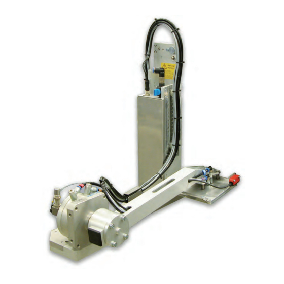
Page 7: Overview
Product Description Overview Throttle valves Vacuum/Support air Fig. 2 Overview front side 1 Setting screw - stopper for the swing movement 8 Shutoff valve 2 Sensors - End position of the swing cylinder 9 Base plate - Printer/Applicator 3 Throttle valves - Speed of the swing cylinder 10 Sensor - Product detecting 4 Knurled screw for attaching the applicator to the printer 11 Blow tube for supporting air... - Page 8 Product Description Valves and control 16 17 Fig. 3 Overview rear side Fig. 4 Overview control elements 1 Setting screw - Limitation of the swing movement 18 Valve blow air 3 Throttle valves - speed of the swing cylinder 19 Valve Vacuum and support air 10 Sensor - Product detecting 20 PCB applicator control Pad (customized)
-
Page 9: Contents Of Delivery
Product Description Contents of Delivery Fig. 5 Contents of delivery Applicator (1) Blow tube - customized (2) Screws - included the pad assembly (3) Pad - customized (4) Documentation Note! Please keep the original packaging in case the applicator must be returned. Attention! The device and printing materials will be damaged by moisture and wetness. -
Page 10: Operation
Operation Standard Operation Check all external connections. Load the material. Ensure that the locking system is locked "Operator's Manual" of the printer. Open the shutoff valve. Attention! Ensure that the pad is not covered by a label when switching on the printer-applicator system. Otherwise the vacuum sensor may be calibrated faultily. - Page 11 Operation Fig. 7 Turn away and Dismount the applicator Attention! Initiation, adjustments and changing of parts is only for qualified service personal only. Attention! Disconnect the printer from the power supply before mounting the applicator! Ensure a stable standing of the printer! Connect the compressed air only after mounting the applicator to the printer! For cleaning the applicator and printer it is sometime necessary to turn away or/and dismount the appli- cator.
-
Page 12: Error Messages
Error Messages Error Messages of the Printer For detailed information about printer errors (e.g. 'Paper out', 'Ribbon out', etc.) Operator's manual of the printer Error treatment: Clear the error results Press the feed key to synchronize the label feed, remove the peeled labels manually ... -
Page 13: Installation
In case of a customer setup with special material the adjustments can deviate from standard values. Then the values in the setup protocol are valid. The standard values for the settings ex-factory are: Connecting on a cab Hermes+ printer, vertical Pressure value of the compressed air 0.45 MPa (4.5 bar) -
Page 14: Mounting The Applicator Parts On The Printer
Installation Mounting the applicator parts on the printer Fig. 8 Mounting Applicator - Printer Note! In case of order a complete / configured system will be mounted some parts. Several steps of mounting dropped. Particularly pad and product sensor. 1. Hang on the control assembly (8) with the female part of hinges (2) at the printer mounted hinges (3). 2. -
Page 15: Mounting The Blow Tube
Installation Mounting the blow tube Fig. 9 Mounting the blow tube It is possible to rotate the blow tube to optimize the support with the support air for the take over procedure of the label from printer to applicator. 1. Loosen screw (1). 2. -
Page 16: Adjustments
Adjustments Vacuum Adjustments With an under pressure (vacuum) will be the label fixed on the pad. This vacuum must be so strong that the label is fixed on the pad and all suction holes of the pad are covered by the label. The vacuum doesn't be so strong that the correct transport of the label from printer to applicator will be risk. This is depend of the label material. The standard value ex factory is -0.6 bar Note! Over the adjustment of the vacuum it is possible that the form feed of the label to the pad could be manipulate. -
Page 17: Blow Tube And Support Air Adjustments
Adjustments Blow Tube and Support Air Adjustments Adjust the support air that the label can constant without swirl come to the pad from the dispense edge of the printer. All blow tube holes which are over the broadness from the label must be covered. The standard value ex factory is 2 bar. - Page 18 Adjustments Measuring point (RP S) of support air Use a manometer with a measurement area -7 to 7 bar for measurement the pressure. MP S: support air (reference value 2 bar) 1. Remove cover and connect the manometer on RP S. - Tube (2) from valve block to blow tube connector.
-
Page 19: Adjusting The Sensors Of The Swing Cylinder
Adjustments Adjusting the sensors of the swing cylinder Fig. 16 Adjusting the sensors of the swing cylinder Close the pressure air support. Switch on the printer. The sensors (4 and 9) detect the end position of the swing cylinder movement. The generated signal is necessary for the next steps in the operation process. -
Page 20: Adjust The Speed Of The Swing Cylinder
Adjustments Adjust the speed of the swing cylinder Fig. 17 Throttle valves on the swing cylinder To adjust the speed of the cylinder movements use the throttle valves 1 and 2 on the swing cylinder. Over the throttle valves will controlled the outflow of the pressure air. Setting screw (1) turning clockwise for a slowly movement of the pad assembly in direction labeling position (B). ... -
Page 21: Adjusting The Product Sensors
Adjustments Adjusting the Product Sensors The product sensor detects the labeling position of the pad in relation to the product. The adjusting of the product sensor is depending of operation mode - stamp on or blow on. The detecting distance of the sensor is 5 - 200 mm from the lower edge of the sensor. -
Page 22: Configuration
Configuration The applicator can be operated in different ways. While the original process stays the same, the operation mode can be chosen within the printer setup. The most important setting is the selection between the operation modes "Stamp on" and "Blow on". Additionally the applicator has different application modes concerning the order of printing and applying within one labeling cycle. -
Page 23: Configuration Parameters Of The Applicator
Configuration Configuration Parameters of the Applicator The configuration parameters of the applicator can be found in the menu Setup > Machine param. Default Parameter Meaning Applicator Configuration parameters of the applicator > Mode of oper. Setting the operation mode Stamp on, Roll on, Blow on Stamp on > Mode of appl. Setting the application mode Print-Apply / Apply-Print Print- Apply Print-Apply:... -
Page 24: Setting The Peel Position
Configuration Setting the Peel Position To optimize the transfer of the labels from the printer to the pad there two different parameters are available for adjusting the peel position. Attention! First adjust the parameter "Peel Position" in the printer configuration. Following adjust the additional peel-off offset in the software. It is very important to follow that procedure for a certain start after label loading and for the re-start after error treatment. -
Page 25: Test Operation
Test Operation Test Mode without Print Job Warning! The pad will immediately be moved in the starting position! Danger of crushing to hand and fingers by the moving pad! Do not reach into the zone of the moving pad and keep long hair, loose clothes, and jewelry distant. Fig. 19 Test mode via Enter key Note! ... -
Page 26: Application Mode
Operation Application mode Labeling the front side, in direction of the transport Label will printed and takeover of the applicator. Pad is swinging in the labeling position (1 and 2). Product touched the pad and will detect over the product sensor. Figure - section 2 and 3 Vacuum will switched off and the label will apply (stamp on or blow on). -
Page 27: Spare Parts
5904544.001 Spring 12.1 5964429.001 Plate 5902241.001 Screw DIN7984-M4x10 12.2 5964438.001 Plate 7.1 5970261.001 Mounting Plate 5902021.001 Screw DIN7991-M3x6 7.2 5970266.001 Mounting Plate Note 3014 L / 3016 L 3014 R / 3016 R Fig. 23 Retainer Assembly - Spare Parts... -
Page 28: Pneumatics Retainer Assembly
33.3 5964614.001 Blow Tube 6" 25, 26: If it is necessary to replace a valve of a device with Note 3014 L / 3016 L 3014 R / 3016 R a serial number up to 9741, replace the entire 2"... -
Page 29: Electronics Retainer Assembly
46.2 5970208.001 Cable 5955575.001 Applicator Control 46.3 5971123.001 Cable 5955586.001 Cable 5970246.001 Sensor Adapter 5971102.001 Cable Retainer 5966417.001 Retainer Note 3014 L / 3016 L 3014 R / 3016 R Tube Cable Fig. 25 Electronics Retainer Assembly - Spare Parts... -
Page 30: Cylinder Assembly
5970116.001 Retainer 5970263.001 Sensor Product Detecting 5907083.001 Stopper 34x34 5907249.001 Shock Absorber 57.1 5970096.001 Lever 57.2 5970094.001 Lever 57.3 5971103.001 Lever Note 3014 L / 3016 L 3014 R / 3016 R Tube Cable Fig. 26 Tamp retainer - Spare Parts... -
Page 31: Drawings
Drawings 10.1 Block Diagram EEPROM Applicator Control CON 1 CON 1 SUB-D 9 Sensor Product Detecting Interface to Printer Applicator Interfaces Sensor Start Position Swing Cylinder Sensor End Position Swing Cylinder CON 2 CON 1 Valve Block Fig. 27 Block diagram... -
Page 32: Pneumatic Drawing
Drawings 10.2 Pneumatic drawing Fig. 28 Pneumatics... -
Page 33: Index
Index Adjusting the sensors .......19 Retainer Assembly......27 Adjust the speed .......20 Application mode ......26 Safety Instruction ........4 Safety marking........5 Block Diagram ........31 Sensors of the swing cylinder ...19 Blow pad ..........6 Spring loaded tamp pad .....6 Blow tube ........15, 17 Tamp pad ..........6 Cleaning ...........10 Tamp retainer........30...
Need help?
Do you have a question about the 3014 and is the answer not in the manual?
Questions and answers