Table of Contents
Advertisement
Quick Links
INSTALLATION AND OPERATING INSTRUCTIONS:
1 Supporting documents
NOTE:
The documents mentioned below are available for download on our website www.zimmer-group.de. Only the
documents currently available on the website are valid.
• Catalogs, drawings, CAD data, technical data
• Detailed installation and operating instructions
• General Terms and Conditions of Business with specifications for the warranty entitlement
2 Safety notes
CAUTION:
Non-compliance may result in severe injuries!
Injuries/malfunctions can occur especially with:
• Crushing during installation due to an unsecured mounting piece
Protection against crushing as a result of low element stroke (max. 0,4 mm).
Protection by the use of bistable design engineering.
• Missing or loose mounting screws
• Failure to switch off the working medium during assembly or repair work on the element
• Human error
• Failure to observe the safety and warning instructions during installation and start-up
These installation and operating instructions are intended for installation and maintenance technicians as
well as design engineers requiring the element for an application. Please read all installation and operation
instructions carefully before start-up and pay special attention to the following hazard warnings and notes.
3 Proper use
NOTE:
The element should only be used in its original state with its original accessories, without any unauthorized
changes and within the scope of the defined parameters for use. Zimmer GmbH shall accept no liability for any
damage caused by improper use.
In accordance with EN ISO 13849-1, the LKE element is a safety-related component of control systems. Furthermore, we
can confirm the manufacture of the product using the basic and proven safety principles (Appendix D.1 and D.2 of EN
13849-2) and thus define the LKE element as a proven component in accordance with EN 13849-1, Chap. 6.2.4, Par. b).
The element can be used without any control engineering measures in control systems of Category B or 1; for category 2
control systems, a test channel must be provided. For use in higher control categories, the control must be implemented
using multiple channels, where each channel must implement the safety function for itself.
The element may not be used in any application other than those approved by the manufacturer.
Without additional protection or control engineering measures, the element may not:
• be installed in facilities that are used for transporting people (e.g. elevators).
• be used in vehicles.
• be used underwater or in other fluids.
• be used in a corrosive environment (for example, in connection with acids).
• come in contact with abrasive media (such as grinding dust).
• come in direct contact with food.
• be used in areas with a potentially explosive atmosphere.
For questions regarding use of the LKE series element, please contact Zimmer GmbH.
4 Personnel qualification
DANGER:
Never open the housing. Intervention is not permitted and can lead to serious injuries!
Warranty and disclaimer.
The manufacturer, ZIMMER GmbH, accepts no liability in the event of damage to property or injuries to
persons.
The installation, start-up, maintenance and repairs may be undertaken only in accordance with these installation and
operating instructions and only by qualified personnel who have the professional expertise and know the conditions, as
well as the dangers, of the machine into which the element is being installed.
5 Product description
The element of the LKE series is a bistable element and is designed for static clamping or fixing of system components on
profile rail guides. Based on the self-locking functional principle, when the clamp is closed there is no need for any supply
voltage for the actuator to maintain the holding force. This means that in an open state, the only signal present is the DIR
signal (refer to the table found under Point 6, "Connections").
Profile rail guide
1
2
Eccentric gear
3
Clamping jaws
Housing
4
5
Electric drive
6
Sliding block
Emergency actuation
7
8
Electrical connecting cable
9
Adjustment screw
Motor housing
10
The element is provided with a serial number
bn
bn
is located on the housing of the element. If possible, use this serial
number
bn
with your project and/or end customer to achieve a clear
and, above all, consistent assignment in the event of an update or
overhaul.
bm
The part number
can be found using the serial number
NOTE:
The clamping process during a movement (dynamic) can lead to destruction or damage of the profile rail or the
element itself.
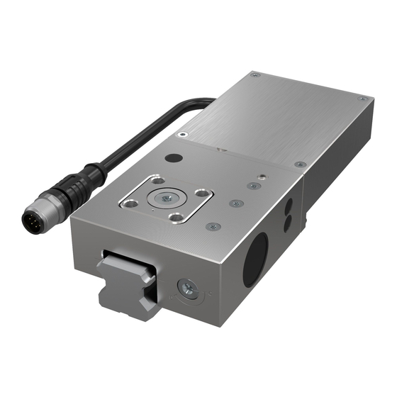
Clamping element, electric, LKE series
Fig. 1: LKE element
Fig. 2: LKE element cutaway view
. The serial number
bn
.
Zimmer GmbH • Im Salmenkopf 5 • D-77866 Rheinau, Germany • Phone:+49 7844 9138 5556 • Fax: +49 7844 9138 80 • www.zimmer-group.de
6 Connections
The element is connected via an 8-pin M12x1 plug cable.
7
Installation
NOTE:
Ensure accessibility for emergency actuation
The element does not have any guide characteristics!
► Check the element for any damage before installing it.
• The element may only be used in conjunction with linear rail carriages.
► The mounting surface of the element (sliding block
mounting piece.
This enables the maximum possible holding force to build up. The adjacent motor housing
by the mounting piece.
• Make sure the mounting pieces are sufficiently rigid (refer to section 7.1).
• Install the element using 4 screws.
• Use screws with a minimum strength class of 8.8.
Observe tightening torques
http://www.schrauben-normen.de/anziehmomente.html
• Note the screw-in depth of the screws. If the screws are screwed in too far, they can block the floating
bearing Malfunction
7.1
Design of the mounting piece
INFORMATION:
The holding force is the maximum force that can be generated in the axial direction.
The specified holding forces are tested on every clamping and braking element before delivery using a slightly
lubricated rail (ISO VG 68). Using other oil or lubricating substances can influence the coefficient of friction, which
can cause a loss of holding force in individual cases.
In course of further development, technical changes are reserved.
NOTE:
Make sure the mounting piece is sufficiently rigid.
The user alone is responsible to ensure that the mounting piece is sufficiently rigid in terms of the 2006/42/
EC Machinery Directive. ZIMMER GmbH accepts no liability for any subsequent damage to the element or
subsequent injuries to persons.
► Make sure that the mounting faces (sliding block
► The roughness of the surface (contact surface) of the
mounting piece should not exceed the value Ra = 3,2 µm.
► The extension cord, which lengthens the connecting cable
must not exceed a length of 10 m and must be shielded.
► The electric connecting cable
8
the mounting piece. The cable must be installed in such a way
that the cable cannot rub against the rail or get pinched.
► The 3D data for the profile rails is not necessarily true to detail
in the area of the rail groove. Refer to the catalog or product
selection on our website (www.zimmer-group.com/com/plt) to
see whether an element fits on the selected rail.
7.2
Installation procedure
NOTE:
If the mounting screws are tightened when the element is not closed, the element can shift and therefore be
unable to achieve the optimum holding force! Furthermore, the guide rail could become damaged.
INFORMATION:
The element is allowed to be closed only if the associated profile rail is between the contact surfaces!
• There must be no control voltage present when an electrical connecting cable
disconnected!
• Avoid changing signals before the specified time (opening/closing), otherwise there may be a malfunction.
• Unauthorized opening of the housing shall void any warranty claim.
If the element is not yet connected to a power supply, the element can be opened and closed manually using the
7
emergency actuation
.
Turning counterclockwise = close
Turning clockwise = open
► Set the element on the linear guide.
If a spacer plate is used, it is inserted between the element
and the mounting piece as level compensation.
► Screw the screws into the tapped holes of the sliding block
and tighten them only slightly.
► The element centers itself as a result of a single cycle.
► Close the element.
► Tighten the mounting screws crosswise using the specified
torque.
► Open the element.
Installation and
Im Salmenkopf
operating instructions
77866 Rheinau, Germany
LKE
+49 7844 9138-5556
Fax: +49 7844 9138 80
DDOC00215
Index d
EN / 2019-05-16
www.zimmer-group.de
1
White
DIR signal, open=1 (24V)/close=0 (0V)
2
Brown Output status "closed"
3
Green
Output status "error"
4
Yellow Voltage supply 24 V / Logic
5
Grey
Output status "open"
6
Pink
Voltage supply 24 V / Motor
7
Blue
Not connect
8
Red
Voltage supply 0 V / GND
7
and of the adjustment screw
9
of the element.
6
+ terminal box
4
) has to be completely covered by the
bl
does not have to be covered
DIN 912 or ISO 4762
6
) are flat (0,03 mm).
8
,
must be relieved of strain at
8
is connected or
6
Advertisement
Table of Contents

Related Manuals for Zimmer LKE Series


Summary of Contents for Zimmer LKE Series
- Page 1 ► The roughness of the surface (contact surface) of the The element of the LKE series is a bistable element and is designed for static clamping or fixing of system components on mounting piece should not exceed the value Ra = 3,2 µm.
- Page 2 EU Machinery Directive 2006/42/EC (Annex II 1 A) Name and address of the manufacturer: 10 Accessories ZIMMER GmbH • Im Salmenkopf 5 • D-77866 Rheinau, Germany • Phone: +49 7844 9138 0 • Fax: +49 7844 9138 80 • www.zimmer-group.de Article number...
Need help?
Do you have a question about the LKE Series and is the answer not in the manual?
Questions and answers