PI NEXACT Stage N-565 Series User Manual
Hide thumbs
Also See for NEXACT Stage N-565 Series:
- Short instructions (4 pages) ,
- User manual (47 pages)
Table of Contents
Advertisement
Quick Links
MP148E
N-565 NEXACT® Stage
User Manual
Version: 1.3.0
PI miCos GmbH, Freiburger Strasse 30, 79427 Eschbach, Germany
Phone +49 7634 5057-0, Fax +49 7634 5057-99, Email info@pimicos.ws, www.pi.ws
Date: 02.03.2020
This document describes the following products:
N-565.160
Precision Linear Stage, 13 mm Travel Range,
PIOne Linear Encoder, 0.5 nm Resolution,
10 N Drive Force,
Dimensions 65 × 80 × 20 mm (W × L × H),
NEXACT® Piezoelectric Walking Drive
N-565.260
Precision Linear Stage, 26 mm Travel Range,
PIOne Linear Encoder, 0.5 nm Resolution,
10 N Drive Force,
Dimensions 65 × 110 × 20 mm (W × L × H),
NEXACT® Piezoelectric Walking Drive
N-565.360
Precision Linear Stage, 52 mm Travel Range,
PIOne Linear Encoder, 0.5 nm Resolution,
10 N Drive Force,
Dimensions 65 × 160 × 20 mm (W × L × H),
NEXACT® Piezoelectric Walking Drive
Advertisement
Table of Contents

Related Manuals for PI NEXACT Stage N-565 Series


Summary of Contents for PI NEXACT Stage N-565 Series
- Page 1 10 N Drive Force, Dimensions 65 × 160 × 20 mm (W × L × H), NEXACT® Piezoelectric Walking Drive PI miCos GmbH, Freiburger Strasse 30, 79427 Eschbach, Germany Phone +49 7634 5057-0, Fax +49 7634 5057-99, Email info@pimicos.ws, www.pi.ws...
- Page 2 PI®, PIC®, PICMA®, PILine®, PIFOC®, PIMag®, PiezoWalk®, NEXACT®, NEXLINE®, NanoCube®, NanoAutomation® © 2020 Physik Instrumente (PI) GmbH & Co. KG, Karlsruhe, Germany. The text, photographs and drawings in this manual are protected by copyright. With regard thereto, Physik Instrumente (PI) GmbH & Co. KG retains all the rights.
-
Page 3: Table Of Contents
Contents About this Document Objective and Target Audience of this User Manual..........1 Symbols and Typographic Conventions..............1 Definition ........................2 Figures ........................2 Other Applicable Documents ..................3 Downloading Manuals ....................3 Safety Intended Use ......................5 General Safety Instructions ..................5 Organizational Measures .................... - Page 4 Discharging the Piezo Actuators of the Drive ............29 Maintenance General Notes on Maintenance ................31 Cleaning the N-565 ....................31 Troubleshooting General Notes on Troubleshooting ................33 Possible Causes and Correction ................34 Customer Service Technical Data 10.1 Specifications ......................37 10.1.1 Data Table ....................
-
Page 5: About This Document
1 About this Document About this Document In this Chapter Objective and Target Audience of this User Manual ..............1 Symbols and Typographic Conventions ..................1 Definition ............................2 Figures ............................2 Other Applicable Documents ......................3 Downloading Manuals ........................3 Objective and Target Audience of this User Manual This manual contains information on the intended use of the N-565. -
Page 6: Definition
1 About this Document INFORMATION Information for easier handling, tricks, tips, etc. Symbol/ Meaning Label Action consisting of several steps whose sequential order must be observed Action consisting of one or several steps whose sequential order is irrelevant List item ... -
Page 7: Other Applicable Documents
If a manual is missing or problems occur with downloading: Contact our customer service department (p. 35). Downloading manuals 1. Open the website www.pi.ws. 2. Search the website for the product number (e.g., P-882) or the product family (e.g., PICMA® bender). -
Page 9: Safety
2 Safety Safety In this Chapter Intended Use ..........................5 General Safety Instructions......................5 Organizational Measures ....................... 6 Intended Use The N-565 is a laboratory device as defined by DIN EN 61010-1. It is intended for indoor use and in an environment which is free of dirt, oil and lubricants. In accordance with its design, the N-565 is intended for single-axis positioning, adjusting and shifting of loads at different velocities. -
Page 10: Organizational Measures
2 Safety Organizational Measures User manual Always keep this user manual available with the N-565. The latest versions of the user manuals are available for download (p. 3) on our website. Add all information from the manufacturer to the user manual, for example supplements or technical notes. -
Page 11: Product Description
3 Product Description Product Description In this Chapter Model Overview ..........................7 Product View ..........................8 Scope of Delivery ......................... 11 Suitable Controllers ........................11 Technical Features ........................12 Model Overview The N-565 is available in the following versions: Model Description N-565.160 Precision Linear Positioning Stage, 13 mm Travel Range, PIOne Linear Encoder,... -
Page 12: Product View
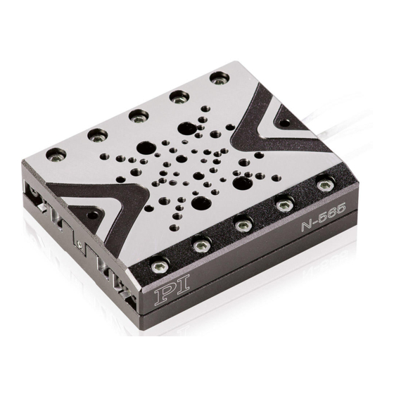
3 Product Description Product View 3.2.1 Product Details Figure 1: N-565 product view Moving platform Cables for connecting sensor and drive to the controller Base body The arrow in the figure shows the positive direction of motion. Version: 1.3.0 MP148E N-565 NEXACT®... -
Page 13: Product Labeling
3 Product Description 3.2.2 Product Labeling Figure 2: Position of the product labeling on the stage Figure 3: Position of the product labeling on the motor and sensor connector N-565 NEXACT® Stage MP148E Version: 1.3.0... - Page 14 3 Product Description Position Labeling Description 1, 3 N-565 / N-565.x60 Product name. Characters following the period identify the model exactly. 414000946 Serial number (example), individual for each N-565 Meaning of the places (counting from left): 1 = internal information, 2 and 3 = year of manufacture, 4 to 9 = consecutive numbers 2, 3...
-
Page 15: Scope Of Delivery
3 Product Description Scope of Delivery Item ID Components N-565 Stage according to order (p. 7) 5870500002 Screw set for mounting of the N-565: 4 M3x16 socket-head cap screws, ISO 4762 2 dowel pins 3 m6 x 8, ISO 2338 ... -
Page 16: Technical Features
3 Product Description Technical Features 3.5.1 Linear Encoder (Sensor) The stage is equipped with an optical linear encoder. For the encoder resolution, refer to the table in the "Specifications" section (p. 37). Optical linear encoders measure the actual position directly (direct metrology). Therefore, errors occurring in the drivetrain such as nonlinearity, backlash or elastic deformation, cannot influence the measurement of the position. -
Page 17: Unpacking
2. Compare the contents with the items listed in the contract and the packing list. 3. Inspect the contents for signs of damage. If parts are missing or you notice signs of damage, contact PI immediately. 4. Keep all packaging materials in case the product needs to be returned. -
Page 19: Installation
5 Installation Installation In this Chapter General Notes on Installation ...................... 15 Mounting the N-565 onto a Surface .................... 18 Setting Up an XY System ......................21 Fixing the Load to the N-565 ......................23 Connecting the N-565 to the Controller ..................25 General Notes on Installation NOTICE Damage from changes in position due to external forces! - Page 20 5 Installation Figure 4: Accessible when the moving platform is driven out: Ruler of the linear encoder Bottom of the moving platform of the N-565 Scale of the linear encoder, do not touch! Figure 5: Accessible when the moving platform is driven out: Ceramic rail of the NEXACT® drive Bottom of the moving platform of the N-565 Ceramic rail of the NEXACT®...
- Page 21 5 Installation NOTICE Damage from mechanical actions! The ruler of the linear encoder is scratch-sensitive and can be damaged by mechanical actions, e.g. from pointed objects. Treat the ruler with extreme care. The ruler is not accessible in the reference position of the moving platform (delivery state). If necessary before installation and demounting: ...
-
Page 22: Mounting The N-565 Onto A Surface
Damage due to unsuitable cables! Unsuitable cables can damage the N-565 and the electronics. Only use cables provided by PI for connecting the N-565 to the electronics. INFORMATION For optimum repeatability, all components must be firmly fixed to each other. - Page 23 5 Installation The mounting holes of the N-565 are intended for the following mounting options: Mounting option Mounting holes, details see "Dimensions" (p. 40) Mounting from above with M3x12 screws Figure 6: N-565, top view: M4 holes (with core hole diameter Ø 3.4 mm and counterbore), for mounting from above with M3 screws Mounting from above with M3x12 screws...
- Page 24 5 Installation NOTICE Screws that are too long! Screws that are inserted too deeply can damage the N-565. Observe the depth of the mounting holes (p. 40). Only use screws of the correct length for the respective mounting holes. NOTICE Protruding screw heads! Protruding screw heads can damage the N-565.
-
Page 25: Setting Up An Xy System
5 Installation Mounting the N-565 on a surface 1. Only for mounting from above: When the required mounting holes in the base body of the N-565 are covered by the moving platform: − Start up the stage (p. 27) and command the moving platform to a suitable position (see user manual of the controller and arrows in the illustration). - Page 26 5 Installation Designations in these instructions: Lower stage: Forms the basis of the multi-axis system (X-axis), is attached to a surface Upper stage: Forms the Y-axis of the multi-axis system, is attached to the lower stage rotated by 90° Requirements ...
-
Page 27: Fixing The Load To The N-565
5 Installation 1. If necessary: Make the required mounting holes in the base body of the upper stage accessible. − Start up the upper stage (p. 27) and perform a reference move to the reference switch (see the user manual of the controller). 2. - Page 28 5 Installation Fixing the load to the N-565 Figure 10: Mounting holes for fixing the load to the moving platform 8 x M2.5 holes with 4 mm thread depth 18 x M2 holes with 3 mm thread depth 4 x M3 holes with 5 mm thread depth For the exact position, see Dimensions (p.
-
Page 29: Connecting The N-565 To The Controller
5 Installation Connecting the N-565 to the Controller Figure 11: N-565: Connections HD Sub-D 15 (m) drive connector Sub-D 15 (f) sensor connector Adapter Sub-D 15 (m) to HD Sub-D 15 (f) Requirements You have read and understood the general notes on installation (p. 15). ... -
Page 31: Startup And Operation
6 Startup and Operation Startup and Operation In this Chapter General Notes on Startup and Operation ..................27 Operating Parameters........................28 Operating the N-565 ........................29 Discharging the Piezo Actuators of the Drive ................29 General Notes on Startup and Operation NOTICE Damage due to collisions! Collisions can damage the stage, the load to be moved, and the surroundings. -
Page 32: Operating Parameters
INFORMATION The repeatability of the positioning is only ensured when the reference switch is always approached from the same side. Recommended controllers from PI fulfill this requirement with their automatic direction detection for reference moves to the reference switch. Operating Parameters If you use the software included in the scope of delivery of the E-861.1A1 controller, the... -
Page 33: Operating The N-565
6 Startup and Operation Operating the N-565 Requirements You have read and understood the general notes on startup and operation (p. 27). You have read and understood the user manual of the controller. You have read and understood the user manual of the PC software. ... -
Page 35: Maintenance
7 Maintenance Maintenance In this Chapter General Notes on Maintenance ....................31 Cleaning the N-565 ........................31 General Notes on Maintenance The N-565 is maintenance-free. Cleaning the N-565 Requirements You have discharged the piezo actuators of the N-565. You have disconnected the N-565 from the controller. Cleaning the N-565 ... -
Page 37: Troubleshooting
8 Troubleshooting Troubleshooting In this Chapter General Notes on Troubleshooting....................33 Possible Causes and Correction ....................34 General Notes on Troubleshooting CAUTION Risk of glare and irritation! The linear encoder of the N-565 uses a class 2 laser according to DIN EN60825-1. Technical data of the laser: L ≤... -
Page 38: Possible Causes And Correction
8 Troubleshooting Possible Causes and Correction Problem Possible Causes Solution Target position is approached Servo-control 1. Switch off the servo-control system too slowly or with overshoot parameters are not immediately. optimally set Target position is not kept 2. Check the settings of the servo-control Large changes in the load ... -
Page 39: Customer Service
9 Customer Service Customer Service For inquiries and orders, contact your PI sales engineer or send us an email (service@pi.de). If you have questions concerning your system, have the following information ready: − Product codes and serial numbers of all products in the system −... -
Page 41: Technical Data
10 Technical Data Technical Data In this Chapter Specifications ..........................37 Maximum Ratings ........................39 Dimensions ..........................40 Pin Assignment ..........................41 10.1 Specifications 10.1.1 Data Table N-565.160 N-565.260 N-565.360 Unit Tolerance Motion Active axes Travel range Velocity, closed-loop mm/s max. -
Page 42: Ambient Conditions And Classifications
10 Technical Data N-565.160 N-565.260 N-565.360 Unit Tolerance Minimum incremental motion 3 Reference switch Optical Optical Optical Miscellaneous Operating temperature range 10 to 50 10 to 50 10 to 50 °C Operating voltage -10 to 45 -10 to 45 -10 to 45 Material Aluminum, black Aluminum, black... -
Page 43: Maximum Ratings
10 Technical Data 10.2 Maximum Ratings The stage is designed for the following operating data: Maximum Operating Maximum Power Maximum Operating Voltage Frequency Consumption 45 V 1500 Hz 40 W N-565 NEXACT® Stage MP148E Version: 1.3.0... -
Page 44: Dimensions
10 Technical Data 10.3 Dimensions Dimensions in mm. Characters used to separate decimal places: Depth and diameter of holes: Period All other dimensions: Comma Figure 12: Dimensions of the N-565 Models N-565.160 N-565.260 N-565.360 Version: 1.3.0 MP148E N-565 NEXACT® Stage... -
Page 45: Pin Assignment
10 Technical Data 10.4 Pin Assignment 10.4.1 Drive Connection The HD Sub-D-15 connector transmits the signals to control the drive. Figure 13: HD Sub-D 15 connector (m) for the drive, mating side Function* Direction Piezo 1 Input Piezo 3 Input Piezo 0 Input Piezo 2... -
Page 46: Sensor Connection
10 Technical Data 10.4.2 Sensor Connection Pin assignment of the Sub-D connector (f) on the N-565 The Sub-D 15 connection transmits the signals from and to the integrated incremental linear encoder ("sensor") and the reference switch. Figure 14: Sub-D 15 connector (f) for sensor, mating side Signal* Function Direction... -
Page 47: Pin Assignment Of The N664B0001 Adapter
10 Technical Data 10.4.3 Pin Assignment of the N664B0001 Adapter The pin assignments for the N664B0001 adapter that is included in the scope of delivery of the N-565 are as follows: Sub-D 15 (m) connector: See "Sensor Connection for N-565" ... -
Page 49: Old Equipment Disposal
PI miCos equipment made available on the market after 13 August 2005 without charge. Any old PI miCos equipment can be sent free of charge to the following address: PI miCos GmbH Freiburger Strasse 30 79427 Eschbach, Germany N-565 NEXACT®... - Page 51 12 EC Declaration of Conformity EC Declaration of Conformity For the N-565, an EC Declaration of Conformity has been issued in accordance with the following European directives: EMC Directive RoHS Directive The applied standards certifying the conformity are listed below. EMC: EN 61326-1 Safety: EN 61010-1 RoHS: EN 50581...
Need help?
Do you have a question about the NEXACT Stage N-565 Series and is the answer not in the manual?
Questions and answers