
Subscribe to Our Youtube Channel
Related Manuals for Grundfos Selcoperm SES 125-2000


Summary of Contents for Grundfos Selcoperm SES 125-2000
- Page 1 GRUNDFOS INSTRUCTIONS Selcoperm SES 125-2000 Electrochlorinator Valid for SES-125, -250, -500, -1000 built from week 37-2015 Valid for SES-2000 built from week 20-2014 Installation and operating instructions...
-
Page 2: Table Of Contents
Checking the mains water supply and (temporary) storage of the Selcoperm system. Start-up and shutdown procedures Only authorised personnel trained by Grundfos are permitted to Checks during operation undertake any work at the system. Appropriate technical Voltage, amperage and air flow readings... -
Page 3: Obligations Of The Operator
The electrodes are guaranteed time-dependent a further three years. Grundfos will replace or refurbish the electrodes during 1.4 Obligations of the operator this period at cost of parts, less a percentage that is equal to the The owner of the building or the operator of the Selcoperm expected life not obtained from the electrodes. -
Page 4: Product Description
Grundfos recommends to follow good practice when handling chemicals, and to use personal protective equipment such as ventilated, enclosed goggles, face shields, chemical aprons, boots and gloves. -
Page 5: Product Overview
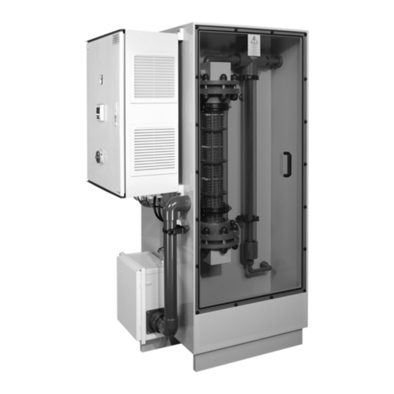
2.2 Product overview Front Left Hydraulic chamber Back Right Electrolysis and degassing chamber Fig. 2 Overview Electrolyser cell Brine injection valve Soft water outlet to brine tank Transparent degassing column 16a Isolating valve Mains water inlet Brine pump 16b Isolating valve Brine inlet water softener Water softener Isolating valve... -
Page 6: Schematic
2.3 Schematic FISA- FISA- DP01 LSA++ LSA+ FISA+ LSA- FISA- LSA-- LSA+ LSA+ LSA+ 4 14 Fig. 3 Schematic Electrolyser cell 16b Isolating valve Brine tank Transparent degassing column Isolating valve Soft water outlet Brine pump 16d Isolating valve Mains water inlet Water softener Internal tray flood switch Brine inlet water softener... -
Page 7: Process Description
2.4 Process description For locating the components, see figures and 3. 2.4.1 Selcoperm Sodium hypochlorite solution (the product) is prepared in a simple batch process, initiated by the level within the product tank (M). The water for the electrochlorinator should be supplied to mains water supply (C) via a double non-return valve. -
Page 8: Technical Data
3. Technical data 3.2 Type key 3.1 Nameplate Example -250 Capacity Max. Nominal [g/h] Grundfos Water Treatment GmbH - Reetzstr. 85 - D-76327 Pfinztal 1800 g/h, 380-415V 50/60HZ 14700VA, 1000 connection: mm 2000 1800 Connection imperial metric Fig. 4 Nameplate... -
Page 9: Dimensions And Weights
3.5 Dimensions and weights 3.5.1 Weights Type 1000 2000 Gross weight [kg] Net weight [kg] 3.5.2 Dimensional drawing 1112 Fig. 5 Dimensional drawing... -
Page 10: Brine Tank Capacities
3.6 Brine tank capacities 3.10 Water softener 3.10.1 General data Gravel requirement Brine tank Salt capacity [kg] [kg] Regeneration 95714317 Salt used [kg] 0.45 95714318 Regeneration time [min] 95714319 Water used per cycle 18.9 95714320 1000 General data (filled with resin beads) 3.7 Temperatures and humidity Shipping weight [kg]... -
Page 11: Electrical Requirements
3.11 Electrical requirements Warning Before making any electrical connections, switch off the power supply and make sure that it cannot be accidentally switched on. All electrical connections must be carried out by a qualified electrician in accordance with local regulations. All electrical connections must be carried out in accordance with the separate wiring diagram delivered with the system. - Page 12 3.11.2 Switching status of relay outputs Signal Relay open Relay closed Running signal System stopped System running System fault Fault No fault Collecting tray signal Liquid in collecting tray No liquid in collecting tray Remote stop signal System stopped System running Emergency stop signal System stopped System running...
-
Page 13: Installation
4. Installation 4.1 Installation drawings 4.1.1 Installation overview 500 - 750 500 - 750 A : A Warning Horizontal ventilation pipework has min. 150 to be installed with a constant upwards incline towards a safe discharge point! Fig. 7 Selcoperm installation Duty/standby dosing pumps Pressure level sensor Product tank and collecting tray... - Page 14 Fig. 8 Product line installation Product tank and collecting tray Product line Selcoperm electrochlorinator 4.1.2 Brine tank Fig. 9 Brine tank Requirements and capacities of brine tank see Soft water inlet (20 mm) Note section 3.6 Brine tank capacities. Minimum gravel level Brine outlets (20 mm) 4.1.3 Venturi tee Fig.
-
Page 15: Installation Notes
10 m in length. For longer distances please ask Grundfos for suitable solutions. The run Water supply connections must be checked to ensure they should rise continuously in an uphill direction towards the safe conform to respective international standards e.g. -
Page 16: Electrical Connection
"AIR FLOW" and "GENERATING TIME" (operating hours) regulations. Contact details Grundfos All electrical connections must be carried out in accordance with the separate wiring diagram Scroll through the screens using the [UP] and [DOWN] keys. -
Page 17: Service Menu 1
Low and high limits normally 20-30 % above GENERATING TIME HIGH and below voltage set point X hrs ALARM TIMER GRUNDFOS X sec INFORMATION: Alarm delay timer normally 30-60 sec. "AIR AIR FLOW m³/hr FLOW" alarm will be factory-set. WWW.GRUNDFOS.COM... -
Page 18: Startup
The brine tank (A) must be kept full with salt at high level. Warning PVD (Pure Vacuum Dried) salt is not suitable for use in Grundfos brine tanks! The water level in the brine tank (A) is maintained by floater valve (21). 6.2 Water softener... -
Page 19: Start-Up And Shutdown Procedures
(1). 1000 12 - 15.5 152 - 155.5 We recommend to perform this check with the Grundfos 2000 24-30 309-315 Selcoperm test kit. See section 7.3.1 Test... -
Page 20: Voltage, Amperage And Air Flow Readings
6.5.3 Checking the product (NaClO solution) 6.8 Alarms We recommend to perform this check with the Grundfos Before testing, enter service menu 1 (see section 5.3 Service Selcoperm test kit. See section 7.3.1 Test kit. menu 1). Set the alarm timer to 10 seconds. This will significantly reduce the testing time. -
Page 21: Maintenance
7. Maintenance 7.2 Maintenance kits The maintenance kit includes parts for maintenance after two For locating the components, see figures and 3. years (maintenance kit for brine pump and for Selcoperm). 7.1 Safety instructions Description Product No. Warning Maintenance kits for systems until 2010 Cleaning and maintenance must only be carried out Selcoperm 125-500 95702281... -
Page 22: Weekly
Check for water hardness by viewing the electrolyser cell (1) Wear protective clothing and goggles and use the when not in operation. There should be no scale present. Grundfos acid cleaning kit! If required, a water hardness test on the softened water can be done. See section 6.5.1 Checking the water... -
Page 23: Fault Finding
8. Fault finding For locating the components, see figures and 3. Fault Display text Possible cause Possible remedy Lack of brine in electrolyser cell (1) Check settings of brine pump (3). Check SG. See section 6.5.2 Checking the salinity of the electrolyte. -
Page 24: Spare Parts Lists
9. Spare parts lists 9.1 Selcoperm electrochlorinator Fig. 16 Overview electrochlorinator spare parts Pos. Product No. Description Pos. Product No. Description 98056656 Electrolyser cell (SES-125) 95727178 Degassing column level sensor 98056729 Electrolyser cell (SES-250) 96688535 Pressure reducing valve 98056755 Electrolyser cell (SES-500) 95727176 Air flow monitor 98056757... -
Page 25: Power Supply And Control Panel
9.2 Power supply and control panel Fig. 17 Power supply and control panel Pos. Product No. Description 95729981 Logic controller, language German 95729982 Logic controller, language English 95729983 Logic controller, language French 95729984 Logic controller, language Spanish 95729985 Logic controller, language Russian 95727184 Temperature sensor 98710813... -
Page 26: Brine Tank
9.3 Brine tank Fig. 18 Brine tank for salt saturation Pos. Product No. Description 98056828 Side entry valve 95727187 3/4" lateral filter 9.4 Product tank Fig. 19 Product tank Pos. Product No. Description 98056894 Tray flood switch 95721859 Pressure level sensor 0-10 V 95723414 Pressure level sensor 4-20 mA Replacement set for tank level sensor... -
Page 27: Disposal
Warning environmentally sound way. Use appropriate waste collection Before dismantling, the system must be completely services. If this is not possible, contact the nearest Grundfos flushed with water in order to remove the chemicals company or service workshop. from the electrolyser cell, the hoses, the pipes and the pumps. - Page 28 Fig. 22 Installation pipework Fig. 23 Safe ventilation point Subject to alterations.
- Page 29 We, Grundfos, declare under our sole responsibility that the product Wir, Grundfos, erklären in alleiniger Verantwortung, dass das Produkt Selcoperm SES 125-2000, to which the declaration below relates, is in Selcoperm SES 125-2000, auf das sich diese Erklärung bezieht, mit den...
- Page 30 Declaration of conformity EAC Установки приготовления гипохлорита натрия типа Selcoperm серии SES, SEP сертифицированы на соответствие требованиям Технических регламентов Таможенного союза: ТР ТС 004/2011 «О безопасности низковольтного оборудования»; ТР ТС 010/2011 «О безопасности машин и оборудования»; ТР ТС 020/2011 «Электромагнитная совместимость технических средств». Сертификат...
- Page 31 Siu Wai Industrial Centre Turkey Poland GRUNDFOS Canada Inc. 29-33 Wing Hong Street & GRUNDFOS POMPA San. ve Tic. Ltd. Sti. 2941 Brighton Road GRUNDFOS Pompy Sp. z o.o. 68 King Lam Street, Cheung Sha Wan Gebze Organize Sanayi Bölgesi Oakville, Ontario ul.
- Page 32 98721013 0817 ECM: 1213971 www.grundfos.com...
Need help?
Do you have a question about the Selcoperm SES 125-2000 and is the answer not in the manual?
Questions and answers