Grundfos Selcoperm SES 125-2000 Instructions Manual
Electrolysis system for 110-1800 g/h cl₂ (equivalent)
Hide thumbs
Also See for Selcoperm SES 125-2000:
Table of Contents
Advertisement
Quick Links
Advertisement
Table of Contents

Related Manuals for Grundfos Selcoperm SES 125-2000


Summary of Contents for Grundfos Selcoperm SES 125-2000
- Page 1 GRUNDFOS INSTRUCTIONS Selcoperm SES 125-2000 Electrolysis system for 110-1800 g/h Cl₂ (equivalent) Installation and operating instructions Selcoperm SES 125-2000 Installation and operating instructions (all available languages) http://net.grundfos.com/qr/i/QR99619753...
- Page 3 Selcoperm SES 125-2000 English (GB) Installation and operating instructions ............4 Deutsch (DE) Montage- und Betriebsanleitung .
-
Page 4: Table Of Contents
Installation ......20 warranty. Grundfos will not be liable for damage or wear to products caused by abnormal operating conditions, accident, abuse, misuse, Installation examples . -
Page 5: Directions For Use
Users The persons responsible for operation and basic maintenance of Selcoperm SES 125-2000 is a complex device used to create the system are referred to as "users" in this document. The users sodium hypochlorite from salt, water and electricity (provided by the must be trained for their tasks by qualified service persons. -
Page 6: Notes
WARNING versions and Non-TÜV versions Indicates a hazardous situation which, if not avoided, could result in death or serious personal injury. Selcoperm SES 125-2000 systems are available in 2 different versions: CAUTION • TÜV versions: Systems in installations that are in conformity Indicates a hazardous situation which, if not avoided, with TÜV demands can be TÜV certified. -
Page 7: Safety Instructions
If you have questions regarding the material resistance, 4.1.4 Hydrochloric acid please contact Grundfos. Hydrochloric acid is used to remove deposits from the electrodes Make sure that leaking chemicals do not cause personal (acid cleaning). -
Page 8: Storage And Handling
Applications other than those described in section Applications are supplier documents. not in accordance with the intended use and are not permitted. The manufacturer, Grundfos, accepts no liability for any damage • Maximum storage time: 2 years from delivery. resulting from incorrect use. -
Page 9: Selcoperm Electrolyser
36 months from delivery. The electrodes are guaranteed time-dependent a further three years. Grundfos will replace or refurbish the electrodes during this period at cost of parts, less a percentage that is equal to the expected life not obtained from the electrodes. -
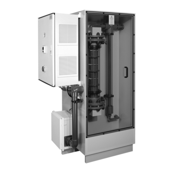
Page 10: System Overview
6.3 System overview 6.3.1 Selcoperm electrolyser Electrolysis cell 15 Brine injection valve Soft water outlet to brine tank Degassing column 16a Isolating valve Mains water inlet Brine pump 16b Isolating valve D1 Brine inlet water softener Water softener 16c Isolating valve D2 Brine inlet dosing pump Water solenoid valve 16d Isolating valve... - Page 11 6.3.2 NaClO solution storage tank xxxxxxxxxxxxxxxxx xxxxxxxxxxxxxxxxx xxxxxxxxxxxxxxxxx xxxxxxxxxxxxxxxxx xxxxxxxxxxxxxxxxx NaClO solution storage tank Tank cap Warning label (see figure Area classification in section Safety concept) Collecting tray Tank NaClO solution inlet NaClO solution overflow NaClO solution outlet to point of application Tray flood switch Tank level sensor Related information...
-
Page 12: Piping And Instrumentation Diagram (Pid)
NaClO solution storage tank level 12a Venturi tee N2 Tank NaClO solution inlet sensor 12b Tank degassing line Display and control Ventilation line outlet to atmosphere 12c Air flow measuring piece Main switch and emergency stop Cell temperature switch Interface customer/Grundfos... -
Page 13: Safety Concept
6.5 Safety concept - If required by local legislation, permanent monitoring of hydrogen leakage by hydrogen sensors with safety shutdown This section refers to the figure in section Selcoperm electrolyser. • Reduction of the zones through ventilation A reliable safety concept for the operation of the whole system is mandatory, because hydrogen is produced as a by-product in the - Parts containing hydrogen are dual-contained and forced- electrolysis cell. -
Page 14: Process Description
Area classification pipework to prevent localised accumulation of hydrogen. An air flow sensor (13) is fitted to shut down the electrolyser in case of a blockage or restriction in the ventilation line (12), or if the sealing cover of the electrolysis and degassing chamber is removed. The electrolyser is fail safe. -
Page 15: Technical Data
7. Technical data 7.1 Selcoperm electrolysis system 7.1.1 General data Sodium hypochlorite concentration 5 - 6.5 g/l (depending on the capacity level) 4 - 4.5 kg NaCl per kg of Cl (equivalent) Salt consumption Approx. 5.5 - 6.5 kWh per kg of Cl (equivalent) Power consumption (AC) 140-170 litres per kg of Cl... -
Page 16: Selcoperm Electrolyser
7.1.7 Brine tank data Gravel Weight (tank + Total weight (filled with gravel, Salt capacity Diameter Height requirement gravel) salt and water) [kg] [mm] [mm] [kg] [kg] [kg] 1020 1030 1000 1050 1040 1630 7.1.8 NaClO solution storage tank data Collecting tray Tank volume Total height... - Page 17 Standard values after a reset of the system. 7.2.2 Electrical data SES-125 SES-250 SES-500 SES-1000 SES-2000 1-phase 1-phase 3-phase + N 3-phase + N 3-phase + N Voltage [V] 1 × 220-240, ± 10 % 1 × 220-240, ± 10 % 380-415, ±...
- Page 18 7.2.6 Dimensional drawing 1138...
- Page 19 7.2.7 Field wiring diagram Selcoperm control panel Single-phase 110 VAC + / 240 VAC + X1:L1 Mains power supply 110 VAC + / 240 VAC - X1:N Product tank and collecting tray Earth X1:PE Tray flood switch of Product tank Tray flood switch of Product tank 24 VDC + X30:7+...
-
Page 20: Installation
8. Installation 8.1 Installation examples 8.1.1 Standard installation example 1 500 - 750 500 - 750 A : A ≥ 150 (measurements in mm) Dosing pump Hydrogen hose NaClO solution storage tank and collecting tray 11a NaClO solution line Selcoperm electrolyser 11b Hydrogen hose centering piece Brine tank Ventilation line... - Page 21 8.1.2 Standard installation example 2 Dosing pump Hydrogen hose NaClO solution storage tank and collecting tray 11a NaClO solution line Selcoperm electrolyser 11b Hydrogen hose centering piece Brine tank Ventilation line Safe ventilation area 12a Venturi tee Drill hole for ventilation pipework 12b Tank degassing line 12c Air flow measuring piece (for manual measurement)
- Page 22 8.1.3 Standard installation example 3 Dosing pump Hydrogen hose NaClO solution storage tank and collecting tray 11a NaClO solution line Selcoperm electrolyser 11b Hydrogen hose centering piece Brine tank Ventilation line Safe ventilation area 12a Venturi tee Drill hole for ventilation pipework 12b Tank degassing line 12c Air flow measuring piece (for manual measurement)
- Page 23 8.1.4 Standard installation example 4 Dosing pump Hydrogen hose NaClO solution storage tank and collecting tray 11a NaClO solution line Selcoperm electrolyser 11b Hydrogen hose centering piece Brine tank Ventilation line Safe ventilation area 12a Venturi tee Drill hole for ventilation pipework 12b Tank degassing line 12c Air flow measuring piece (for manual measurement)
- Page 24 8.1.5 Examples of impermissible installation Do not install any valves or measuring equipment in the NaClO solution line (11a) or tank degassing line (12b). The following installations are impermissible because condensation can form in the hydrogen hose, which leads to blockage of the hydrogen hose or ventilation pipework.
-
Page 25: Installation Requirements
Separate the system from the power supply before working on the system components and lines. Wear the stipulated personal protective equipment. Grundfos accepts no liability for any damage resulting from incorrect installation. 8.2.1 Location • The installation location must be free of vibrations. - Page 26 10 bends. The total height from the foundation of the electrolyser to the ventilation line outlet must not exceed 10 m. For longer distances ask Grundfos for suitable solutions. - Only smooth bends must be used to avoid turbulent air flow and loss of pressure: •...
- Page 27 8.2.12 Air flow measuring piece installation Pos. Description Important installation notes / details The air flow measuring piece is part of the Selcoperm safety Hydrogen hose Install the hydrogen hose at the hose concept and is used to manually check the air flow during clamp connector inside the hydraulic chamber of commissioning and maintenance.
- Page 28 NaClO solution storage tank. The tank interior is classified as zone 2. Even if no Grundfos standard tank is used, the described NaClO solution storage tank setup must be adhered to in order to meet the requirements of the Selcoperm safety concept.
-
Page 29: Electrical Connection
8.2.16 Additional external NaClO solution storage tank installation It is possible to install an additional NaClO solution storage tank downstream the standard NaClO solution storage tank. However this additional tank can never replace the standard NaClO solution storage tank which is required to control the electrolysis process. The additional external equipment (level sensors, transfer pump, etc.) required for this setup must be controlled via a separate control cabinet. -
Page 30: Commissioning
9. Commissioning 9.3 Water softener commissioning The water used to make the sodium hypochlorite must be softened Commissioning must be done by qualified service to less than 20 mg/l CaCO . Hard water will scale the electrodes persons. and reduce efficiency. Wear the stipulated personal protective equipment. -
Page 31: Initial Startup
9.4.1 Setting the water flow rate The water flow rate is shown at flowmeter (6), and can be adjusted with water flow adjustment valve (8). Factory-set Factory-set Total NaClO water meter brine flow Type solution flow flow [l/h] [l/h] [l/h] SES-125 1.7 - 2.1 20.7 - 21.1... -
Page 32: Check Of Voltage, Amperage And Air Flow Readings
9.6 Check of voltage, amperage and air flow readings • If the measured value is too high, reduce the air flow scale stepwise until the measured value is displayed in Active air The readings for the electrolyser can be taken from the display. flow. -
Page 33: Operation
9.8.5 Checking the system for hydrogen gas leakages 10. Operation This task must be performed by qualified service persons. The system may only be operated by authorised and WARNING qualified specialists. Danger of explosion Wear the stipulated personal protective equipment. Death or serious personal injury ‐... -
Page 34: Menu Structure
10.2 Menu structure Button Symbol Menu Main menu Messages • Display of alarms and messages • Information Service menu • Settings -> Language • Settings -> System capacity • Settings -> Tank level • Settings -> Tank / water • Settings ->... -
Page 35: Main Menu - F1
10.7.1 Settings -> Language Description The display language can be selected in this menu. Select your language by pushing the respective flag. Set cursor to start of input field. 10.5 Main menu - F1 System status and system information are shown in this menu. See also section Display and control. - Page 36 Preset value, refers to Grundfos standard tanks for up to 1000 litres. If a higher tank is Set limit values for the air flow. If the set values...
-
Page 37: Operating Hours - F4
10.7.7 Settings -> Time 10.7.8 Manual operation The solenoid valve and the brine pump can be switched on and off Summer and winter time manually in this menu. The solenoid valve and the brine pump are Summer and winter time settings can be made in this menu. displayed with a delay after switching to this menu. -
Page 38: Automatic Operation
1. Switch off power supply at switch (29). 2. Flush and drain the system. 3. Isolate system from water supply with isolating valve (16a). For further advice please contact Grundfos. Related information 11.3 Flushing and draining the system 11.3 Flushing and draining the system For locating the components, see the figures in sections Selcoperm electrolyser and Piping and instrumentation diagram. -
Page 39: Maintenance
(protective clothing, goggles, respirator etc.). Observe the chemical manufacturer's safety data sheets See also the service kit catalogue and Grundfos Product Center (MSDS) and safety instructions of the used chemicals. (https://product-selection.grundfos.com). Safety installations, which have been disabled or removed during maintenance, must be enabled or installed again 12.3 Special tools... -
Page 40: Basic Maintenance Schedule (Users)
12.4 Basic maintenance schedule (users) In the following table, the basic maintenance activities to keep the system free from troubles and avoid breakdowns are described. These activities must be performed by trained users. The intervals for some of the tasks depend on the individual installation and must therefore be defined by the operating company. - Page 41 200-500 ml electrolyte solution to flush the sample line. 4. Dispose of the sample in accordance with local regulations. The salinity can be checked either by measuring the conductivity with the Grundfos conductivity measuring device or by measuring the specific gravity with the Grundfos Selcoperm test kit.
-
Page 42: Advanced Maintenance Schedule (Qualified Service Persons)
12.5 Advanced maintenance schedule (qualified service persons) In the following table, the advanced maintenance activities are described. These activities must be performed by qualified service persons. The position references in the table refer to Piping and instrumentation diagram PID. Before replacing any components, flush the system and drain it. After the system has been drained, it must be recommissioned. - Page 43 Related information 6.4 Piping and instrumentation diagram (PID) 7.2.1 Setpoints 9. Commissioning 9.7 Checking and adjusting the air flow 9.8.5 Checking the system for hydrogen gas leakages 11.3 Flushing and draining the system 12.2 Recommended service parts 12.4.4 Checking and adjusting the salinity of the electrolyte 12.5.5 Acid cleaning 12.5.2 Retightening the DC connections 12.5.1 Checking the system for hydrogen gas leakages 2.
- Page 44 Wear the stipulated personal protective equipment (protective clothing, goggles, respirator etc.). ‐ Observe the chemical manufacturer's safety data sheets (MSDS) and safety instructions of the used chemicals. ‐ Only use the original Grundfos acid cleaning kit and always perform the acid cleaning procedure completely.
-
Page 45: Fault Finding
13. Fault finding 13.2 Low voltage of electrolysis cell Fault message: Cell voltage min For locating the components, see the figures in sections Selcoperm electrolyser and Piping and instrumentation diagram Cause Remedy Related information Too much brine in the • Check the settings of the 6.3.1 Selcoperm electrolyser electrolyte... -
Page 46: Ventilation Failure Max
13.6 Ventilation failure MAX 13.10 Leakage in electrolysis chamber and hydraulic chamber Fault message: Air flow max Fault message: Leakage unit Cause Remedy Cause Remedy The cover of the cell chamber • Replace the cover. is damaged Leakage in a pipe fitting •... -
Page 47: System Is Suddenly Switched Off
This product or parts of it must be disposed of in an environmentally sound way: 1. Use the public or private waste collection service. 2. If this is not possible, contact the nearest Grundfos company or service workshop. The crossed-out wheelie bin symbol on a product means that it must be disposed of separately from household waste. - Page 48 China RoHS 1. China RoHs Selcoperm SES 产品中有害物质的名称及含量 有害物质 部件名称 铅 汞 镉 六价铬 多溴联苯 多溴联苯醚 (Pb) (Hg) (Cd) (Cr6+) (PBB) (PBDE) 控制柜 供水机组 空调 安防系统 灯具 紫外消毒装置(选配) 水质仪表(选配) 本表格依据 SJ/T 11364 的规定编制 O:表示该有害物质在该部件所有均质材料中的含量均在 GB/T 26572 规定的限量要求以下。 X: 表示该有害物质至少在该部件的某一均质材料中的含量超出 GB/T 26572 该规定的限量要求。 该产品环保使用期限为...
- Page 49 • RoHS Directives (2011/65/EU and 2015/863/EU). Standard used: EN IEC 63000:2018. This EU declaration of conformity is only valid when published as part of the Grundfos installation and operating instructions (publication number 99619753). Bjerringbro, 01.March 2022 Jimm Feldborg Head of PD IND...
- Page 50 The Restriction of the Use of Certain Hazardous Substances in Electrical and Electronic Equipment Regulations 2019. Standard used: EN IEC 63000:2018.. This UK declaration of conformity is only valid when accompanying Grundfos instructions. UK Importer: Grundfos Pumps ltd. Grovebury Road, Leighton Buzzard, LU7 4TL. Bjerringbro, 01.March 2022...
- Page 51 Ukrainian declaration of conformity GB: Ukrainian declaration of conformity We, Grundfos, declare under our sole responsibility that the products to which the declaration below relates, are in conformity with Ukrainian resolutions, standards and specifications to which conformity is declared, as listed below:...
- Page 52 Bjerringbro, 4/March/2022 Jimm Feldborg Head of PD IND Grundfos Holding A/S Poul Due Jensens Vej 7 8850 Bjerringbro, Denmark GB: Manufacturer and person empowered to sign the Ukrainian declaration of conformity UA: Виробник та особа, уповноважена підписати українську декларацію відповідності...
- Page 53 Operating manual EAC Selcoperm SES типоразмеров: SES-125, SES-250, SES-500, SES-1000, SES-2000 Руководство по эксплуатации Руководство по эксплуатации на данное изделие является составным и включает в себя несколько частей: Часть 1: настоящее «Руководство по эксплуатации». Часть 2: электронная часть «Паспорт. Руководство по монтажу и эксплуатации» размещенная на сайте...
- Page 54 SES-1000, SES-2000, անցել են Մաքսային միության տեխնիկական կանոնակարգի պահանջներին համապատասխանության հաստատմանը` TР ТС 004/2011« Ցածր լարման սարքավորումների անվտանգության մասին »; TР ТС 010/2011 «Մեքենաների եւ սարքավորումների անվտանգության մասին»; TР ТС 020/2011 «Տեխնիկական սարքավորումների էլեկտրամագնիսական համատեղելիություն»: http://net.grundfos.com/qr/i/ 99619721 10000284606 0320 ECM: 1283182...
- Page 55 Tel.: +387 33 592 480 Centre Turkey Fax: +387 33 590 465 29-33 Wing Hong Street & 68 King Lam GRUNDFOS Pumper A/S GRUNDFOS POMPA San. ve Tic. Ltd. Sti. www.ba.grundfos.com Street, Cheung Sha Wan Strømsveien 344 Gebze Organize Sanayi Bölgesi E-mail: grundfos@bih.net.ba...
- Page 56 99619753 02.2023 ECM: 1312088 www.grundfos.com...
Need help?
Do you have a question about the Selcoperm SES 125-2000 and is the answer not in the manual?
Questions and answers