
Subscribe to Our Youtube Channel
Related Manuals for Grundfos Selcoperm SES Series


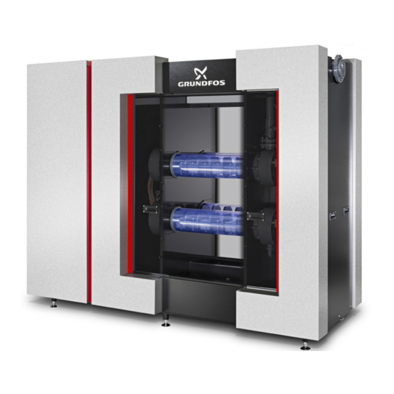
Summary of Contents for Grundfos Selcoperm SES Series
- Page 1 GRUNDFOS INSTRUCTIONS Selcoperm SES Electrolysis system for 5-45 kg/h Cl (equivalent) Installation and operating instructions Other languages http://net.grundfos.com/qr/i/98647157...
-
Page 2: Table Of Contents
English (GB) Installation and operating instructions Original installation and operating instructions 5.2.9 Space requirements Rectifier CONTENTS 5.3.1 Technical data for air-cooled rectifier 5.3.2 Technical data for water-cooled rectifier Page DC cable set General information Degassing and storage tank Documentation package 5.5.1 Connections Scope of this document... -
Page 3: General Information
The Selcoperm electrolysis system comprises a number of 8.5.29 System configuration components. The core components must be purchased from 8.5.30 Configuration of system capacity Grundfos to ensure the compliance with the Selcoperm safety 8.5.31 Configuration of tank volume concept. These core components are: 8.5.32 Configuration of interface •... -
Page 4: Target Group
Selcoperm system. the persons must be precisely defined by the operating company. • Obtain instructions from Grundfos specialists on all service If necessary, the persons must be trained. work relating to the system. Operating company •... -
Page 5: Symbols On The Product
- When checking the system for gas leakages, use If you have questions regarding the material hydrogen detectors. Do not use a match or a resistance, please contact Grundfos. flame. Make sure, that leaking chemicals do not cause Hydrogen is an explosive gas and lighter than air. When liberated personal injury or damage to property. -
Page 6: Hydrochloric Acid
2.1.4 Hydrochloric acid 3. Storage and handling Hydrochloric acid is used to remove deposits from the electrodes (acid cleaning). Observe the supplier documents for the components. All supplier documents are part of the documentation WARNING package delivered with the system. Chemical hazard Death or serious personal injury 3.1 Storage... -
Page 7: Product Description
Applications other than those described in section 4.1.1 Intended are not in accordance with the intended use and are not permitted. The manufacturer, Grundfos, accepts no liability for any damage resulting from incorrect use. Unauthorised structural modifications to the system may result in serious personal injury and damage to equipment. -
Page 8: Overview Of Components
4.1.4 Overview of components ATEX zone 2 radius 1-2 m Fig. 2 Installation scheme of a Selcoperm electrolysis system Pos. Component Description Water softener The water softener provides the softened mains water required for the electrolysis. Chiller and/or An optional chiller or heater can be used to provide the correct mains water temperature. heater Brine tank The brine tank is used for preparation and storage of brine. -
Page 9: Safety Concept
4.1.5 Safety concept Explosion protection by avoiding the explosive zones: • Preventing or limiting inside the unit This section refers to fig. 2. – Redundant level sensors to ensure liquid filled parts A reliable safety concept for the operation of the whole system is mandatory, because hydrogen is produced as a by-product in the •... - Page 10 Labelling recommendations A warning sign must be placed on the outside of the degassing and storage tank near the manhole. The purpose of the sign is to warn people of an explosive atmosphere, so that they can take the necessary precautions. We recommend that the sign is accompanied by a written notice, e.g.
-
Page 11: Piping And Instrumentation Diagram (Pid)
V0.10 V0.06 LSAH 0.01 GND3 GND2 Fluid line Electrical line FSAL FSAL 0.26 0.16 Electrical signal line Interface customer (white) | Grundfos (black) DP 0.10 DP0.11 Fig. 5 Piping and Instrumentation Diagram (PID). Example of a system with electrolyser SES-45000... - Page 12 Pos. Description Instrument type Pos. Description 0.01 Level switch in collecting tray LSAH Brine dosing station 0.02 Water inlet flow sensor FIAHL Cell line 1 0.03 NaClO outlet temperature sensor TIAHL C1.1 Electrolysis cell 1 0.05 Water inlet solenoid valve C1.2 Electrolysis cell 2 0.16...
- Page 13 Connections SES type Pos. Description Connection type 5000 7500 10000 15000 20000 30000 45000 Soft water inlet Union connection DN 25 DN 25 DN 25 DN 25 DN 40 DN 40 DN 40 Brine inlet Union connection DN 20 DN 20 DN 20 DN 20 DN 25...
-
Page 14: Process Description
4.1.7 Process description After flushing is completed, brine pump (DP0.10) stops and solenoid valve (0.05) closes. The flow of electrolyte through the This section refers to fig. 5. electrolysis cells stops. The degassing fan (EF4.01) stops after a General information few minutes. -
Page 15: Selcoperm Electrolyser
Grundfos will replace or refurbish the electrodes during this period at cost of parts, less a percentage that is equal to the Grundfos Water Treatment GmbH - Reetzstr. 85 - D-76327 Pfinztal expected life not obtained from the electrodes. If this option is... - Page 16 Fig. 9 Overview components SES-20000 to SES-45000 Pos. Description Chemically resistant PEHD frame with collecting tray Easily removable powder-coated housing Horizontal electrolysis cells with transparent PVC pipe for easy process monitoring and visual electrode check. Several sensors monitor the level and temperature of the liquid as well as the voltage and temperature of all direct-current (DC) connections. Lockable hydraulic chamber with shut-off valves and adjusting valves, temperature sensors, flow sensors and leakage sensors, sample valves for brine and sodium hypochlorite solution, and a connection for acid cleaning.
-
Page 17: Overview Hydraulics Ses-5000 To Ses-15000
4.2.4 Overview hydraulics SES-5000 to SES-15000 1.03 1.02 0.03 1.09 C1.2 1.04 C1.1 1.01 V0.09 GND3 V0.05 1.10 1.11 V0.06 V0.10 V1.02 0.05 0.01 0.02 V0.04 V1.01 V0.02 V0.01 V0.07 V0.08 Fig. 10 Overview hydraulics SES-5000 to SES-15000 Pos. Description Pos. -
Page 18: Overview Hydraulics Ses-20000 To Ses-45000
4.2.5 Overview hydraulics SES-20000 to SES-45000 2.09 0.03 3.09 1.09 2.03 3.03 C2.2 C3.2 2.04 2.02 3.04 1.03 3.02 C2.1 1.02 2.01 C1.2 1.04 C3.1 3.01 C1.1 1.01 GND3 V0.05 3.10 2.10 1.10 / 1.11 V0.04 V3.01 V2.01 V0.10 V1.01 V3.02 V2.02 V0.09... - Page 19 Pos. Description Pos. Description 0.01 Level switch in collecting tray Cell line 1 0.02 Water inlet flow sensor C1.1 Electrolysis cell 1 0.03 NaClO outlet temperature sensor C1.2 Electrolysis cell 2 0.05 Water inlet solenoid valve Cell line 2 Protection against accidental contact C2.1 Electrolysis cell 3 1.01...
-
Page 20: Signal Diagram
Power supply BY COSTUMER Poten al free contact Ven a on Fan Start / Stop GSM OPTIONAL Duty Poten al free contact Remote maintenance by GRUNDFOS Fault signal 3 phases + PE Power supply* EF 4.02 230V AC Poten al free contact... -
Page 21: Rectifier
4.3 Rectifier 4.5.2 Components The rectifier converts the alternating current (AC) from the power supply into the direct current (DC) needed to run the Selcoperm electrolyser. In case of a failure, the rectifier shuts down. The communication between the Selcoperm electrolyser and the rectifier is designed redundantly (Profinet and hardwired) for the safety shutdown functions. -
Page 22: Brine Dosing Station
4.6 Brine dosing station 4.7 Water softener The brine is dosed with digital dosing pumps. To ensure reliable The water softener provides the softened mains water required brine dosing, the dosing station comprises a duty pump and a for the electrolysis. standby pump. -
Page 23: Components
4.11.1 Components 5.1.2 Salt specification Use food-grade granular/pellet salt (98.5 % NaCl) according to EN 14805 type 2 with following minimum requirements: Max. mass fraction Parameter Symbol for dry salt [mg/kg] Iron 10.0 Manganese 10.0 Bromide 100.0 Calcium 100.0 Magnesium 100.0 5.1.3 Ambient conditions Permissible ambient temperatures (min./max.) -
Page 24: Selcoperm Electrolyser
5.2 Selcoperm electrolyser 5.2.1 General data Sodium hypochlorite concentration 0.8 % Max. salt consumption 3.5 kg NaCl per kg of Cl (equivalent) Max. power consumption (DC/AC)* 4.6 / 5.4 kWh per kg of Cl (equivalent) Soft water consumption 125 litres per kg of Cl (equivalent) Soft water inlet pressure 3-5 bar (depending on the capacity level) -
Page 25: Setpoints
5.2.4 Setpoints The following table shows typical values expected upon commissioning. Please note that these values may need to be adjusted due to salt and water quality on site. No. Setpoint SES- 5000 7500 10000 15000 20000 30000 45000 Capacity [g/h] 5000 7500... -
Page 26: Dimensions Ses-5000 To Ses-15000
5.2.7 Dimensions SES-5000 to SES-15000 2050 1060 367.5 Fig. 17 Dimensions SES-5000 to SES-15000. Dimensions in mm 5.2.8 Dimensions SES-20000 to SES-45000 2800 1190 Fig. 18 Dimensions SES-20000 to SES-45000. Dimensions in mm 5.2.9 Space requirements SES-5000, -7500, -10000, -15000 SES-20000, -30000, -45000 4060 5300... -
Page 27: Rectifier
5.3 Rectifier 5.3.1 Technical data for air-cooled rectifier Enclosure class: IP20 Max. relative humidity 75 % (non-condensing): Permissible ambient temperature +10 / +40 °C for operation (min. / max.): Fig. 20 Example of air-cooled rectifier Input voltage Current per Dimensions Weight Power loss Air flow... -
Page 28: Technical Data For Water-Cooled Rectifier
5.3.2 Technical data for water-cooled rectifier Enclosure class: IP20 Max. relative humidity 75 % (non-condensing): Permissible ambient temperature for +10 / +40 °C operation (min. / max.): Fig. 21 Example of water-cooled rectifier Input voltage Cooling water flow Current per Dimensions Weight Power loss... -
Page 29: Degassing And Storage Tank
5.5 Degassing and storage tank Volume Diameter Height Air flow Power rating* SES type [mm] [mm] [kW] SES-5000 1000 1500 0.55 SES-7500 1000 2000 0.55 SES-10000 1300 1500 0.55 SES-15000 1600 1500 SES-20000 1800 1600 1200 SES-30000 2000 1900 1800 SES-45000 2200 2300... -
Page 30: Chiller
5.8 Chiller Supply voltage: 400 V, 50/60 Hz (3 phases + PE) Max. water temperature inlet: 30 °C Water temperature outlet: 15 °C Ambient temperature range: 10-40 °C (type OLB), 5-45 °C (type cBoxX, Arctic) Capacity Flow level Cl Cooling Power Current Length... -
Page 31: Acid Cleaning Station
5.11 Acid cleaning station • 300-litre acid tank with collecting tray • DMX 460-4 dosing pump with single-phase motor (230 V, 50 5.12 Gas warning system • Wall-mounted IP65 control panel with simultaneous display of up to four gas sensors. Ambient temperature up to 55 °C. •... -
Page 32: Installation
Wear the stipulated personal protective equipment. treated mains water should be used. Grundfos accepts no liability for any damage For flow rates see section 5. Technical data. The tables do not resulting from incorrect installation. -
Page 33: Connective Pipework
• The standard DC cable length from the rectifier to the Selcoperm electrolyser is limited to 10 m. For longer DC cables contact Grundfos. • The power loss of the rectifier leads to an increase of the ambient temperature in the installation room. Ensure sufficient air conditioning. -
Page 34: Degassing And Storage Tank
The piping must be installed as direct and straight as possible, with no dips and no more than 10 m in length. For longer distances ask Grundfos for suitable solutions. – Only smooth bends should be used to avoid turbulent air flow: 4.13... -
Page 35: Connection Of Venturi Nozzle (Vn) And Flow Sensor (4.13)
• The T-piece (TP) must be installed with the connection of level 6.2.14 Connection of venturi nozzle (VN) and flow sensor switch (4.04) pointing down. The level switch connection can (4.13) be rotated up to ± 30 ° to adjust the switching level. See fig. 25. -
Page 36: Dismantling And Reassembling The Selcoperm Electrolyser Housing
6.3 Dismantling and reassembling the Selcoperm Dismantling electrolyser housing Remove the parts in the following order. SES 5000-15000: This section describes only the dismantling and reassembling of the parts that must be removed for the electrical and hydraulic • (60), (110), (90), (100), (10), (40). installation. -
Page 37: Electrical Connection
6.4 Electrical connection NaClO solution line level switch (4.04) Wiring: Minimum 2 x 0.5 mm WARNING This circuit is intrinsically safe. Use a separate cable Electric shock duct. Death or serious personal injury Extend the cable of the plug as required for the - Before making any electrical connections, switch individual installation. -
Page 38: Commissioning
7. Commissioning 7.1.2 Brine tank This section refers to fig. 2. The commissioning must be done by certified service The brine tank (C) is used for preparation and storage of brine. persons. Wear the stipulated personal protective equipment. CAUTION The setpoints given in section 5.2.4 Setpoints must Splashing brine solution... - Page 39 Calibrating the tank level sensor (4.10) 5. Remove sensor cover (5). 6. Dismantle the display (6-8). For the calibration of the sensor the degassing and 7. Press button (10) for at least 3 seconds. storage tank must be empty. – The minimum level is now calibrated. Observe the separate documents delivered with the 8.
-
Page 40: Preparing The Brine Dosing Station (Bds)
7.1.4 Preparing the brine dosing station (BDS) The flow rate is adjusted with the cell inlet adjusting valves (V1.01, V2.01, V3.01). 1. Adjust all manual valves to normal operation. 1. Open water inlet valve (V0.01). 2. Deaerate the brine dosing station. See separate manual. 2. -
Page 41: Checking And Adjusting The Soft Water Flow And The Salinity Of The Electrolyte
Grundfos conductivity The LEDs (1) on all level switches must be off. measuring device or by measuring the specific gravity with the Grundfos Selcoperm test kit. Adjusting the level switch (with filled piping) See section 9.2.1 Test kit. -
Page 42: Checking And Adjusting Naclo Level Switch (4.04)
7.2.6 Checking and adjusting NaClO level switch (4.04) 7.3 Switching to operation mode "Automatic" The level switch is installed on the T-piece (TP) in the NaClO The electrolyte that has entered the degassing tank solution line. To check the level switch, electrolyte must flow during the first commissioning steps does not contain through the T-piece. -
Page 43: Checking The Alarms
7.4 Checking the alarms 7.4.2 Selcoperm electrolyser The final step in commissioning is to check the alarms. The Check the soft water flow alarm system must be in operating state "Automatic". 1. Make sure the system is in operating state "Automatic". To shorten the duration of the checks, the alarm times can be 2. -
Page 44: Operation
8. Operation 8.2.2 Main switch of Selcoperm electrolyser The main switch on the Selcoperm electrolyser switches off the power supply of all components powered via the Selcoperm The system must only be operated by authorised and electrolyser control cabinet. These are: qualified persons. -
Page 45: Touchscreen
8.5 Touchscreen 8.5.2 Keyboard The input is done via a keyboard. All fields with white background The Selcoperm electrolyser, the brine dosing station and the are input parameters which can be changed. Fields with grey degassing and storage tank with degassing fan are controlled via background cannot be changed. -
Page 46: Colours
8.5.3 Colours The status of the different components is shown with different colours on the touchscreen. Colour Description Grey Component switched off or inactive. Green Component switched on or active without fault. Yellow Component manually deactivated. Faulty component. 8.5.4 Acknowledge fault messages In case of a fault, the dialogue "Unacknowledged fault messages"... -
Page 47: Menu Structure
8.5.5 Menu structure Button / Button / Button / Main menu Submenu 1 Submenu 2 Submenu 3 symbol symbol symbol section System 8.5.6 overview Overview rectifier 8.5.12 Settings rectifier 8.5.13 Overview cell 8.5.7 lines Detail single cell 8.5.8 Detail double 8.5.9 cells Settings cell line... -
Page 48: System Menu
8.5.6 System overview Symbol Description The menu "System overview" is shown after startup and during section normal operation of the system. It shows system information and the status of the system. Solenoid valve. Next to the symbol the name (see PID) is displayed. Menu action Required user level Flow sensor. - Page 49 8.5.7 Overview cell lines 8.5.8 Detail single cell This menu gives an overview of all cell lines of the system. This menu is displayed, if the system has only one cell Detail (SES-5000 or SES-7500). Otherwise see section 8.5.9 double cells Menu action Required user level The menu shows all relevant data of the cell.
- Page 50 8.5.10 Settings cell line 8.5.11 Settings system In this menu, the settings of the selected cell line can be viewed In this menu, the settings of the system can be viewed and and changed. changed. Menu action Required user level Menu action Required user level Parametrising staff...
- Page 51 8.5.12 Overview rectifier 8.5.13 Settings rectifier This menu gives an overview of the rectifier. In this menu, the settings of the rectifier can be viewed and changed. Menu action Required user level Menu action Required user level Access menu No login required Parametrising staff Access menu Parametrising staff...
- Page 52 8.5.14 Overview brine pumps 8.5.15 Overview tank This menu gives an overview of the brine pumps of the brine This menu gives an overview of the degassing and storage tank dosing station. The display below is shown in systems with two and the degassing fan.
- Page 53 8.5.16 Settings tank level 8.5.17 Overview fans In this menu, the settings of the degassing and storage tank can This menu gives an overview of the degassing fans of the be viewed and changed. degassing and storage tank. The display below is shown in systems with two degassing fans.
-
Page 54: Language
8.5.18 System menu 8.5.19 Language This menu provides information on the manufacturer and the In this menu, the display language can be set. system as well as menus for general settings, management and configuration. Menu action Required user level Users Access menu Menu action Required user level... -
Page 55: Time / Date Setting
8.5.20 Time / Date setting 8.5.21 User administration In this menu, the time and date settings can be viewed and In this menu, the user settings can be viewed and changed. changed. Menu action Required user level Menu action Required user level Administrators Access menu Parametrising staff... -
Page 56: Service Menu
8.5.22 Service menu 8.5.23 Service I/O Values This menu and its submenus are for service persons only. This menu shows information on all inputs and outputs of the system. Menu action Required user level Menu action Required user level Commissioning staff Access menu Commissioning staff Access menu... -
Page 57: Service Power Supply
8.5.24 Service Power Supply 8.5.25 Service Cell Lines This menu shows information on the internal power supply. This menu shows the cell lines and process settings and is used for commissioning of the system. See section Commissioning. Menu action Required user level Menu action Required user level Commissioning staff... -
Page 58: Service Acid Cleaning
8.5.27 Service Acid Cleaning 8.5.28 Message management This menu is used to perform the acid cleaning to remove scale In this menu, the system messages can be managed. on the electrodes. The menu guides you step by step through the acid cleaning process. -
Page 59: System Configuration
8.5.29 System configuration 8.5.30 Configuration of system capacity In this menu, the submenus for the configuration of the system In this menu, the system capacity and the brine dosing station can be opened. can be configured. Menu action Required user level Menu action Required user level Parametrising staff... -
Page 60: Configuration Of Tank Volume
8.5.31 Configuration of tank volume 8.5.32 Configuration of interface In this menu, the tank volume and degassing fans can be In this menu, the interface can be configured. configured. Menu action Required user level Menu action Required user level Commissioning staff Access menu Administrators Access menu... -
Page 61: Settings Alarm Delays
8.5.33 Settings alarm delays 8.5.34 Settings delay-/flushing times In this menu, the alarm delay times can be viewed and changed. Each time the system enters or leaves the operating state "Production", the delay times in this menu are used for starting Menu action Required user level and stopping the respective components. -
Page 62: Settings Operating Hours Counter Plant
8.5.36 Settings Operating hours Counter plant 8.5.35 Start and stop delays The system has several operating hours counters. Start delays Each time the system is manually or automatically set to Menu action Required user level operating state "Production", it performs the following steps from top to bottom: Parametrising staff Access menu... -
Page 63: Settings Operating Hours Counter Lines
8.5.37 Settings Operating hours Counter lines The system has several operating hours counters. Menu action Required user level Parametrising staff Access menu Commissioning staff Reset values Fig. 74 Settings Operating hours Counter lines Display text Description Operating time of the acid cleaning pump. This Acid pump pump is part of the separate acid cleaning station. -
Page 64: Maintenance
9. Maintenance 9.2 Special tools 9.2.1 Test kit 9.1 Safety instructions Test kit for SES, comprising: The basic maintenance tasks must be performed by • Measuring cylinder trained users. • Total hardness test for titrimetric determination of the water The advanced maintenance tasks must only be hardness performed by certified service persons. -
Page 65: Basic Maintenance Schedule (Users)
9.2.1 Test kit. 9.3.2 Checking the water hardness of the softened water For details on the conductivity measuring device, see We recommend to perform this check with the Grundfos data booklet: http://net.grundfos.com/qr/i/98721404 Selcoperm test kit. See section 9.2.1 Test kit. -
Page 66: Advanced Maintenance Schedule (Certified Service Persons)
9.4 Advanced maintenance schedule (certified service persons) In the following table, the advanced maintenance activities are described. These activities must be performed by certified service persons. The position references in the table refer to the PID. See fig. 5. Before replacing any components, flush the system and drain it. See sections: •... -
Page 67: Retightening The Dc Connections
9.4.2 Retightening the DC connections Rigid copper bars Perform the following steps for all relevant DC connections. This task must be performed by certified service persons. 1. Switch off the main switch of the rectifier. WARNING 2. Remove sensor (1). Electric shock 3. -
Page 68: Replacing The Gaskets In The Electrolysis Cells And In The Naclo Solution Line
9.4.3 Replacing the gaskets in the electrolysis cells and in 9.4.4 Dismantling and reassembling level switches (1.09, the NaClO solution line 2.09, 3.09) This task must be performed by certified service persons. A defective level switch can be dismantled and reassembled as follows. -
Page 69: Dismantling And Reassembling Level Switch (4.04)
The acid cleaning of the electrodes is performed via a semi-automatic process controlled by the Selcoperm electrolyser. The Grundfos acid cleaning station is prepared for electrical connection to the Selcoperm electrolyser control cabinet. The special socket is on the left bottom of the Selcoperm electrolyser control cabinet. -
Page 70: Decommissioning
1. Place the Grundfos acid cleaning station near to the 10. Decommissioning Selcoperm electrolyser. 10.1 Short-term decommissioning up to 4 weeks – Observe the length of the electrical and hydraulic lines. 1. Push [ 2. Make sure the hydrochloric acid used for the acid cleaning is of high grade, free from fluoride and in the concentration –... -
Page 71: Flushing The System With Softened Water
10.4 Flushing the system with softened water 10.6 Flushing the brine dosing station This task must be performed by certified service persons. 1. Push [ Use softened water for flushing. – The system stops. 2. Open menu "Service Cell Lines". See section 8.5.5 Menu structure. -
Page 72: Fault Finding
11. Fault finding If the result of a check requires change, repair or adjustment of the system, call certified service persons. The position references in the table refer to the components overview and the PID. See figs. and 5. Fault Display text Possible cause Possible remedy (certified service persons) - Page 73 Fault Display text Possible cause Possible remedy (certified service persons) • Low water inlet pressure • Contact the local authorities. • Water inlet flow sensor (0.02) • Clean or replace the sensor. damaged or polluted Water flow too • Filter in pressure reducing •...
-
Page 74: Spare Parts
12. Spare parts To ensure safe and reliable operation, always use original spare parts from Grundfos. 12.1 Selcoperm electrolyser Product number SES type Pos. Description 5000- 20000- 15000 45000 Bracket A 99047504 99133224 Bracket B 99047506 99133230 Bracket C 99047511... -
Page 75: Hydraulic Spare Parts
12.1.1 Hydraulic spare parts V0.09 V0.05 1.10 1.11 V0.06 V0.10 V1.02 0.05 0.01 0.02 V0.04 V1.01 V0.02 V0.01 V0.07 V0.08 Fig. 85 SES-5000 to SES-15000 V0.05 3.10 2.10 1.10 V0.04 V3.01 V2.01 V0.10 V1.01 V3.02 V2.02 V0.09 V1.02 V0.06 0.05 V0.01 0.02 0.01... -
Page 76: Electrolysis Cells, Dc Connection And Sensors
12.1.2 Electrolysis cells, DC connection and sensors 2.09 3.09 1.09 C2.1 C2.2 1.01-1.04 2.01-2.04 3.01-3.04 0.03 1.01-1.04 2.01-2.04 3.01-3.04 C3.1 C1.2 C3.2 C1.1 Fig. 87 Electrolysis cells, DC connection and sensors For SES type Pos. Description Product number Electrolysis cells C1.1, C2.1 Electrolysis cell 1 - 5000 g/h 99047026... -
Page 77: O-Ring Sets
12.1.3 O-ring sets For SES type Description Product number X X X O-ring set for piping (NaClO outlet and T-piece) 99047273 O-ring set for piping (NaClO outlet and T-piece) 99047275 X X X O-ring set for piping (NaClO outlet and T-piece) 99055042 X X X X O-ring set for hydraulic chamber... -
Page 78: Rectifier
12.3 Rectifier Product Description number Relay 99070935 Watchdog relay 99070936 12.4 Degassing and storage tank and exhaust air line 4.12 EF4.01 EF4.02 4.10 Fig. 90 Degassing and storage tank For SES type Pos. Description Product number 4.10 X X X X X X X Level sensor 99047296 4.12... -
Page 79: Acid Cleaning Station
- The system must be dismantled by authorised and qualified persons. This product or parts of it must be disposed of in an environmentally sound way. Use appropriate waste collection services. If this is not possible, contact the nearest Grundfos company or service workshop. Subject to alterations. - Page 80 Declaration of conformity GB: EU declaration of conformity DE: EU-Konformitätserklärung We, Grundfos, declare under our sole responsibility that the product Wir, Grundfos, erklären in alleiniger Verantwortung, dass das Produkt Selcoperm SES 5000-45000, to which the declaration below relates, is in Selcoperm SES 5000-45000, auf das sich diese Erklärung bezieht, mit den...
- Page 81 Siu Wai Industrial Centre Turkey Poland GRUNDFOS Canada Inc. 29-33 Wing Hong Street & GRUNDFOS POMPA San. ve Tic. Ltd. Sti. 2941 Brighton Road GRUNDFOS Pompy Sp. z o.o. 68 King Lam Street, Cheung Sha Wan Gebze Organize Sanayi Bölgesi Oakville, Ontario ul.
- Page 82 98647157 0517 ECM: 1209547 www.grundfos.com...
Need help?
Do you have a question about the Selcoperm SES Series and is the answer not in the manual?
Questions and answers