Table of Contents
Advertisement
Quick Links
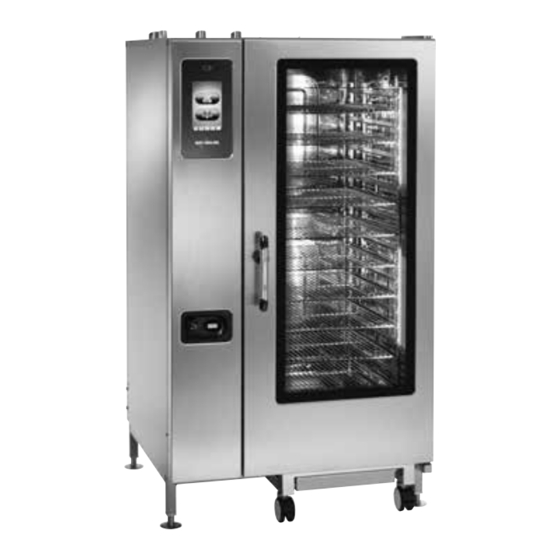
CT PROFORMANCE™
Operation, Maintenance, Troubleshooting, Wiring Diagrams
M N - 3 5 9 4 9
•
R e v
0 4
CT CLASSIC™
•
0 6 / 1 6
•
C o m b i t h e r m ®
TECHNICAL MANUAL
CTP6-10E
CTP10-10E
CTP7-20E
CTP10-20E
CTP20-10E
CTP20-20E
CTC6-10E
CTC10-10E
CTC7-20E
CTC10-20E
CTC20-10E
CTC20-20E
S e r i e s
•
T e c h n i c a l
CTP6-10G
CTP10-10G
CTP7-20G
CTP10-20G
CTP20-10G
CTP20-20G
CTC6-10G
CTC10-10G
CTC7-20G
CTC10-20G
CTC20-10G
CTC20-20G
S e r v i c e
a n d
T r a i n i n g
M a n u a l
Advertisement
Chapters
Table of Contents


Need help?
Do you have a question about the COMBITHERM CTC Series and is the answer not in the manual?
Questions and answers