Table of Contents
Advertisement
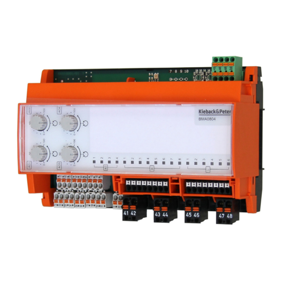
BMA0804 Input/output module
Application
The input/output module with 8 analog inputs and 4 analog
outputs receives analog signals in the DDC4000e
automation system and activates analog control functions.
Manual/automatic rotary switch for controlling the 4 analog
outputs. In manual mode, the output signal can be set in
10% increments 0..100% (0(2)..10 V DC).
LED displays for the operating states of the inputs and
outputs.
Communication is controlled via LED.
Label carrier for system-specific description.
The power supply and the CAN bus are electrically
isolated.
Data is transferred between the central unit and the input/
output module via CAN bus.
The input/output module can be connected to an existing
switch cabinet bus or fieldbus.
Content
Important Information Regarding Product Safety ..................................................................................................2
Item........................................................................................................................................................................3
Technical Data.....................................................................................................................................................3
Dimensions ..........................................................................................................................................................5
Connection...........................................................................................................................................................5
Installation..............................................................................................................................................................7
Mounting ................................................................................................................................................................8
Removal.................................................................................................................................................................8
Function and operation ..........................................................................................................................................9
Commissioning ....................................................................................................................................................10
LED displays......................................................................................................................................................11
Kieback&Peter GmbH & Co. KG
Tempelhofer Weg 50, 12347 Berlin/Germany
Telefon: +49 30 60095-0, Telefax: +49 30 60095-164
www.kieback-peter.de, info@kieback-peter.com
J
Product Description
BMA0804
Page
2.60-80.804-01-EN | 2019-01-17
Advertisement
Table of Contents

Related Manuals for Kieback&Peter BMA0804


Summary of Contents for Kieback&Peter BMA0804
-
Page 1: Table Of Contents
Product Description BMA0804 BMA0804 Input/output module Application The input/output module with 8 analog inputs and 4 analog outputs receives analog signals in the DDC4000e automation system and activates analog control functions. Manual/automatic rotary switch for controlling the 4 analog outputs. In manual mode, the output signal can be set in 10% increments 0..100% (0(2)..10 V DC). -
Page 2: Important Information Regarding Product Safety
Important Information Regarding Product Safety Safety Instructions This data sheet contains information on installing and commissioning the product "BMA0804". Each person who carries out work on this product must have read and understood this data sheet. If you have any questions that are not resolved by this data sheet, you can obtain further information from the supplier or manufacturer. -
Page 3: Item
Product Description BMA0804 Item BMA0804 Input/output module with 8 analog inputs and 4 analog outputs with manual/automatic rotary switch 0..100% for the analog outputs Technical Data Nominal voltage 12..24 V DC ± 10%; 2.5 W Inputs and outputs ■ 4 analog outputs, 0(2)..10 V DC; maximum 2.5 mA ■... - Page 4 Product Description BMA0804 Connection terminal ■ Spring-loaded terminals, printers ■ All terminals can be inserted with conductor end sleeves of 10 mm length ■ Twisting two conductors is not permitted, twin wire-end ferrules can be used Input terminals Output terminals...
-
Page 5: Dimensions
Product Description BMA0804 NOTE You can find more information on the sensor types in the “Temperature Sensor Tables” product description (1.10-90.100-01). Dimensions 143,5 60,0 Connection - Two support terminal blocks, terminals “81” to “88” and terminals “91” to “98” 6(3) A 230V~... - Page 6 Product Description BMA0804 Connection for the actuators and sensors 0..10VDC 0..10VDC 24V 0V Y 24V 0V 24V 0V A 0V A KP10 500k Connection examples - Connection of actuators using the support clamps (3 conductors) BMA0804 6(3) A 230V~ 6(3) A 230V~...
-
Page 7: Installation
Product Description BMA0804 - Connection of several input/output modules via CAN bus Can- Can+ 12..24V= BMA0804 BMA0804 BMD1204 NOTE The terminal block terminal “17” through terminal “20” (feed-through terminals) can be inserted and disconnected without interruption. Installation CAUTION This product description contains the specific settings and functions of the input/output module. In addition to these instructions, the product descriptions of other system components, such as the DDC4000e automation station, are to be observed. -
Page 8: Mounting
Product Description BMA0804 Fieldbus When connecting the fieldbus, use a cable of at least type JY(St)Y 2x2x0.8 Lg: two x two wires, twisted to a pair with plastic insulation and an electrostatic shield with a wire diameter of at least 0.8 mm. -
Page 9: Function And Operation
Product Description BMA0804 Function and operation (1) Manual / automatic rotary switch = auto, 0 ..50..100 = manual operation (2) Combi LED (green, red) CAN bus (3) Address switch (4) Freely configurable LEDs (5) Status LEDs of inputs and outputs Manual/Automatic Mode You can switch to the corresponding operating mode using the manual/automatic rotary switch (1). -
Page 10: Commissioning
Product Description BMA0804 NOTE On delivery, the address “00” is set, which means: - No bus communication - No parameterization possible - Manual operation is effective. The 4 analog outputs can be switched in 10% increments (0..10 V DC) . In automatic rotary switch position, the output is 0 V DC. -
Page 11: Led Displays
Product Description BMA0804 LED displays LED CAN Bus LED status (combination Meaning Cause LED) Module not in operation No operating voltage or operating voltage too low Yellow on (green LED and red Module in operation, but Bus line short circuit (with respect to... - Page 12 Product Description BMA0804 2.60-80.804-01-EN | 2019-01-17 Page 12 / 12...
Need help?
Do you have a question about the BMA0804 and is the answer not in the manual?
Questions and answers