Table of Contents
Advertisement
Issue 2012-05-09
Product Description
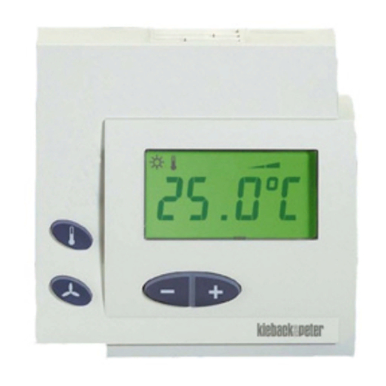
DDC111 and DDC111-2 room control modulel
Application
The room control modules are used together with the technolon® RCNxxx-L
or FBR110-L room controllers. A room control module can be connected to
each technolon® room controller.
DDC111-2 with LCD display for indication of room temperature and operating
buttons for manual setting of the room temperature setpoint and switching
between three fan levels.
The DDC111 room control module also has operating buttons for switching
between day, night and stand-by modes.
Content
Important Information Regarding Product Safety ..................................................................................................2
Item........................................................................................................................................................................3
Technical Data.....................................................................................................................................................3
Accessories (not included in delivery) .................................................................................................................3
Dimensions ..........................................................................................................................................................4
Connection...........................................................................................................................................................4
Mounting ................................................................................................................................................................5
Operation ...............................................................................................................................................................6
DDC111-2 Operation ...........................................................................................................................................6
DDC111 Operation ..............................................................................................................................................7
Änderungen vorbehalten - Contents subject to change - Sous réserve de modifications - Reservado el derecho a modificación - Wijzigingen
voorbehouden - Con riserva di modifiche - Innehåll som skall ändras - Změny vyhrazeny - Zmiany zastrzeżone - Возможны изменения -
A változtatások jogát fenntartjuk - 保留未经通知而改动的权力
Kieback&Peter GmbH & Co. KG
Tempelhofer Weg 50, 12347 Berlin/Germany
Telefon: +49 30 60095-0, Telefax: +49 30 60095-164
www.kieback-peter.de, info@kieback-peter.com
Datasheet 1.10-51.111-01-EN
DDC111, DDC111-2
DDC111-2
DDC111
Page
A
Advertisement
Table of Contents

Subscribe to Our Youtube Channel
Related Manuals for Kieback&Peter DDC111


Summary of Contents for Kieback&Peter DDC111
- Page 1 FBR110-L room controllers. A room control module can be connected to each technolon® room controller. DDC111-2 with LCD display for indication of room temperature and operating buttons for manual setting of the room temperature setpoint and switching between three fan levels.
-
Page 2: Important Information Regarding Product Safety
This data sheet contains information on installing and commissioning the product "DDC111, DDC111-2". Each person who carries out work on this product must have read and understood this data sheet. If you have any questions that are not resolved by this data sheet, you can obtain further information from the supplier or manufacturer. -
Page 3: Item
■ Symbol display to indicate operating mode ■ Fan levels DDC111-2 operating buttons button: Switches to temperature mode for setting the room temperature setpoint button: Switches to fan mode for setting the fan level button: Sets the room temperature setpoint or allows manual setting of... -
Page 4: Dimensions
Datasheet 1.10-51.111-01-EN Issue 2012-05-09 DDC111, DDC111-2 Product Description Dimensions 82,5 28,3 Connection Z178/2 DDC111-2 DDC111 15 cm Z178 10 m Page 4 / 8... -
Page 5: Mounting
Issue 2012-05-09 Datasheet 1.10-51.111-01-EN Product Description DDC111, DDC111-2 Mounting WARNING Contact with live parts of electrical domestic installation can cause death due to electric shock. Mounting/removal may only be carried out when power is switched off. The room control module can be mounted on the wall or onto a flush-mounted box. -
Page 6: Operation
Datasheet 1.10-51.111-01-EN Issue 2012-05-09 DDC111, DDC111-2 Product Description Operation DDC111-2 Operation Displays Function symbols depend on operating mode: Day mode Night mode Stand-by mode Fan levels Automatic switching via central program or presence detector LCD display depends on configuration: ■... -
Page 7: Ddc111 Operation
Issue 2012-05-09 Datasheet 1.10-51.111-01-EN Product Description DDC111, DDC111-2 DDC111 Operation Displays Function symbols depend on operating mode: Day mode Night mode Stand-by mode Fan levels Automatic switching via central program or presence detector LCD display depends on configuration: ■ Room temperature (actual value) with function symbol ■... - Page 8 Datasheet 1.10-51.111-01-EN Issue 2012-05-09 DDC111, DDC111-2 Product Description Stand-by mode Stand-by mode can be switched on by a presence detector or manually only in day mode, e.g., when leaving a room. Switching on stand-by mode: ■ Press the button: Function symbol is displayed.
Need help?
Do you have a question about the DDC111 and is the answer not in the manual?
Questions and answers