Table of Contents
Advertisement
Advertisement
Table of Contents

Subscribe to Our Youtube Channel
Related Manuals for dallmeier SMAVIA IPS 10000


Summary of Contents for dallmeier SMAVIA IPS 10000
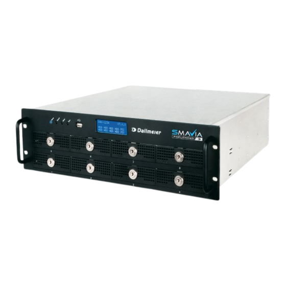
- Page 1 Service English Appliance IPS 10 000 Rev. 1.0.1 / 2018-12-19...
- Page 2 Third-party trademarks are named for information purposes only. Dallmeier electronic respects the intellectual property of third parties and always attempts to ensure the complete identification of thirdparty trademarks and indication of the respective holder of rights. In case that protected rights are not indicated separately, this circumstance is no reason to assume that the respective trademark is unprotected.
-
Page 3: Table Of Contents
Import Parameters ..................17 HDDs ......................19 Identify ......................19 8.1.1 Information Dialog ..................19 8.1.2 Display ......................20 Procedure .....................20 Exchange ......................22 Power Supply Modules................25 Identify ......................25 9.1.1 Information Dialog ..................25 9.1.2 Display ......................26 9.1.3 Status LED ....................26 Deactivation ....................27 Exchange ......................27 Maintainance ....................30 www.dallmeier.com... -
Page 4: Introduction
For instructions on using basic functions of the software (for users with no technical knowledge) Operation For instructions on using all features of the software (for users with no technical knowledge) Configuration Instructions for configuring the software (for trained system integrators) www.dallmeier.com... -
Page 5: Typographical Conventions
Expressions in bold/italics generally indicate a control element on the device (switches or labels) or on its user interface (buttons, menu entries). Paragraphs in italics provide information on basic principles, special features and efficient procedure as well as general recommendations. www.dallmeier.com... -
Page 6: Safety Instructions
System Components Only use internal components that have been tested and approved by Dallmeier. Inappropriate internal components may cause malfunctions, damages and data loss and may result in the loss of warranty. - Page 7 The housings of the units may only be opened by qualified personnel for commissioning, inspection, maintenance and repair. Disposal Do not dispose waste electrical and electronic equipment into the household trash. Disconnect the units from the power supply. Remove all connected devices. Return the units to your respective sales partner. www.dallmeier.com...
-
Page 8: General Notes
The appliance will not start after a com- plete shutdown. The battery on the mainboard must be replaced only by authorized personnel. Contact for an exchange the Dallmeier service. CAUTION Injury due to explosion hazard! ... -
Page 9: Login
In order to access the configuration interface of the appliance, proceed as follows: Move the mouse pointer to the bottom of the screen. The Login button is displayed. Abb. 4-1 Click Login. The virtual keyboard is displayed. Enter the password. Confirm with OK. www.dallmeier.com... - Page 10 SMAVIA Appliance The configuration interface is displayed. Abb. 4-2 Make the required settings (see below). Click Close in order to exit the configuration interface. www.dallmeier.com...
-
Page 11: Remote Login
Select the required appliance. Open the context menu with a right-click. Click NetConfig3. The connection is established. Abb. 4-3 Login Mode User Login Enter User Name and Password. Click Login. Login Mode Group Login Enter the Password. Click Login. www.dallmeier.com... - Page 12 SMAVIA Appliance The configuration interface is displayed. Abb. 4-4 Make the required settings (see below). Click Close in order to exit the configuration interface. www.dallmeier.com...
-
Page 13: Licenses
Open the Licenses dialog via System > Info > Licenses. Abb. 5-2 Make sure that the feature or function is selected as active. Check the functionality of the feature or function. Note that more settings are required under certain circumstances. www.dallmeier.com... -
Page 14: Update
Term of License The duration of the maintenance license is displayed in the software‘s info dialog and can be accessed via the network (PService3). Open the SW-Maintenance dialog via System > Info > Service. Abb. 6-1 www.dallmeier.com... -
Page 15: Implementation
The update is completed after a final restart of the appliance. While the update is performed, no settings or adjustments should be made. The storage medium should be removed only after the full completion of the update (restart). www.dallmeier.com... -
Page 16: Systemparameter
The system parameters can be exported. After export they can be archived and modified to specific requirements. In addition to the system parameters, various log and protocol files are stored. Open the Save Configuration dialog via System > System Parameters > Save Configuration. www.dallmeier.com... -
Page 17: Import Parameters
SMAVIA Recording Server. NOTICE Data loss! System failure! Inappropriate or incorrectly modified system parameters can lead to the loss of recordings and a permanent system fault. Open the Restore Configuration dialog via System > System Parameters > Restore Configuration. www.dallmeier.com... - Page 18 Note the detailed explanations in the dialog. Click Search USB stick if required. Select the required storage medium as a Source. Select the relevant import option. Finally, click OK in order to start the import. The saved system parameters will be restored. www.dallmeier.com...
-
Page 19: Hdds
HDD is active and OK HDD is defective yellow HDD is not active and OK (RAID spare HDD) orange HDD is in recovery process (RAID) Check the status of the hard disk drives. Identify the defective hard disk drive. www.dallmeier.com... -
Page 20: Display
The defective hard disk drive can be replaced during operation (hot-swap). Proceed as described below, to ensure the highest possible data security: Note that • new HDDs must be tested and released for mounting by Dallmeier (HDD white list on www.dallmeier.com). • new HDDs may not be formatted or partitioned. - Page 21 The new hard disk drive is used as the spare hard disk drive (SSS). The recovery of the previous spare hard disk drive (ooo) and the recording continues. Abb. 8-4 Note the information on the display. Note that recovering of a 4000 GB hard disk drive can last up to 100 hours. www.dallmeier.com...
-
Page 22: Exchange
Unlock the HDD drawer unit with the key. Abb. 8-6 Pull the HDD drawer unit carefully out of the housing. Remove the cover plate mounted in the HDD drawer unit. CAUTION Risk of injury from sharp edges! Use care when installing the HDD drawer unit. www.dallmeier.com... - Page 23 Mount the hard disk drive with the 4 screws. NOTICE Possibility of data loss! Always replace a defective HDD with a HDD from the same production series with identical firmware. Abb. 8-8 Insert the HDD drawer unit into the guide rail. www.dallmeier.com...
- Page 24 Make sure not to cant. Do not use any force. Abb. 8-10 Make sure the HDD drawer unit and the housing are flush. Lock the HDD drawer unit with the key. The new hard disk drive is initialized as described above. www.dallmeier.com...
-
Page 25: Power Supply Modules
Open the Info dialog via System > Info. Select the Power Supply tab. Abb. 9-1 grey Power supply unit is not mounted green Power supply is active and okay Power supply is defective/switched off Check the status of the power supply modules. www.dallmeier.com... -
Page 26: Display
The status of the power supply modules is also indicated by the green LED on the front of the module. Abb. 9-3 Green LED lights up Power supply module switched on and OK Green LED not lit Power supply module switched off or defective www.dallmeier.com... -
Page 27: Deactivation
If the device is powered by two redundant power supply modules, one can be exchanged during operation. Turn off the defective power supply module with the appropriate power switch. Remove the power cable. Abb. 9-5 Loose the screws at the top of the power supply module. www.dallmeier.com... - Page 28 Take care not to cant. Do not use any force. WARNING Serious danger by electric shock! Do not grip to the open shaft of the power supply module. Insert no tools in the open shaft of the power supply module. www.dallmeier.com...
- Page 29 Connect the power cable. Turn on the new power supply module with the appropriate power switch. The power supply module is put into operation automatically. The device is powered from the redundant power supply modules with equal parts of tension. www.dallmeier.com...
-
Page 30: 10 Maintainance
Cleaning If it is necessary to clean the device, observe the following notes: NOTICE > Clean the housing (outside) with a soft, dry and antistatic cloth. > Do not use detergents. > Do not use microfiber cleaning cloths. www.dallmeier.com...
Need help?
Do you have a question about the SMAVIA IPS 10000 and is the answer not in the manual?
Questions and answers