Table of Contents
Advertisement
Quick Links
Advertisement
Table of Contents

Subscribe to Our Youtube Channel
Related Manuals for ALIBI ALI-NT4002R


Summary of Contents for ALIBI ALI-NT4002R
- Page 1 ALI-NT4002R, ALI-NT2002R 2MP Optical - Thermal Network Cameras User Manual ALI-NT2002R camera ALI-NT4002R camera PLEASE READ THIS MANUAL BEFORE USING YOUR CAMERAS, and always follow the instructions for safety and proper use. Save this manual for future reference. ALI-NT4002R-NT2002R_UM 190930...
- Page 2 ALIBI and the ALIBI logo are trademarks of Observint. Microsoft, Windows, and Internet Explorer are either registered trademarks or trademarks of Microsoft Corporation in the United States and/or other countries.
- Page 3 Use of the product only in strict compliance with the local electrical safety regulations. Refer to technical specifications for • detailed information. Input voltage should meet both the SELV (Safety Extra Low Voltage) and the Limited Power Source with 24 Vac or 12 Vdc • according to applicable standards. ALI-NT4002R, ALI-NT2002R Cameras User Manual...
- Page 4 Do not connect several devices to one power adapter. Adapter overload may cause over-heating or a fire. • Make sure that the plug is firmly connected to the power socket. When the product is mounted on wall or ceiling, the device •...
-
Page 5: Table Of Contents
2.5 ALI-NT4002R - Adjust the camera pan, tilt and rotation ....... - Page 6 TABLE OF CONTENTS 2.8 Configure System Settings ............33 2.8.1 Configure camera basic information .
- Page 7 Thermal Emissivity Chart ............95 ALI-NT4002R, ALI-NT2002R Cameras User Manual...
- Page 8 NOTES viii...
-
Page 9: Overview
SECTION 1 Overview The Alibi Security ALI-NT4002R (bullet) and ALI-NT2002R (turret) thermal and optical network cameras include a built-in GPU which support an intelligent behavior analysis algorithm to provide high precision video content analytics (VCA) detection and real- time alarms. It is useful for fire-prevention purposes in indoor space such as engine rooms, ATMs, conference rooms, warehouses, museums, train stations, power stations, etc. -
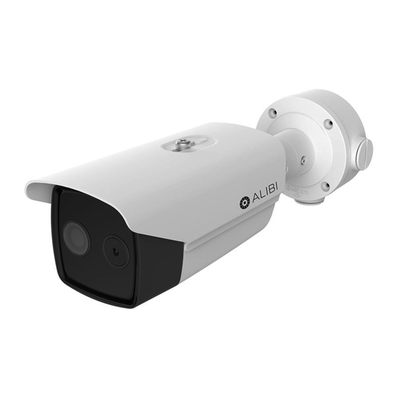
Page 10: Ali-Nt4002R Camera
Camera body Reset, microSD card slot addess on underside camera body Optical camera lens Thermal camera lens ALI-NT4002R camera with junction box 1.2.1 Specifications Thermal Module Image Sensor Vanadium Oxide Uncooled Focal Plane Arrays Max. Resolution 160 × 120 (the resolution of output image is 320 × 240) Pixel Interval 17 μm... - Page 11 Audio Compression G .711u / G.711a / G.722.1 / MP2L2 / G.726 / PCM IPv4/IPv6, HTTP, HTTPS, 802.1x, Qos, FTP, SMTP, UPnP, SNMP, DNS, DDNS,NTP, RTSP, RTCP, RTP, TCP, UDP, IGMP, ICMP, DHCP, Protocols PPPoE ALI-NT4002R, ALI-NT2002R Cameras User Manual...
-
Page 12: Dimensions
Analog Video Output 1.0 V[p-p] / 75Ω, PAL / NTSC / BNC Application Programming Open-ended API, support ISAPI and third-party management platform Client Alibi Central Management Software (ACMS), ACMS Lite Web Browser Microsoft Internet Explorer 9 or later General Menu language... -
Page 13: Ali-Nt2002R Camera
1920 × 1080 Image Sensor 1/2.7” Progressive Scan CMOS Min. Illumination Color: 0.002 Lux @ (F1.2, AGC ON), B/W: 0.0002 Lux @ (F1.2, AGC ON) Shutter Speed 1s to 1/100,000s Lens (Focal Length) 6 mm ALI-NT4002R, ALI-NT2002R Cameras User Manual... - Page 14 SECTION 1: OVERVIEW Field of View 53° × 30° (H × V) 120 dB WDR Day & Night IR cut filter with auto switch Image Function Bi-spectrum Image Fusion Fusion view of thermal view and overlaid details of the optical channel Picture in Picture Combines details of thermal and optical image PIP, overlay thermalimage on optical image Smart Function...
-
Page 15: Dimensions
Analog Video Output 1.0V [p-p] / 75Ω, PAL / NTSC / BNC Application Programming Open-ended API, support ISAPI and third-party management platform Client Alibi Central Management Software (ACMS), ACMS Lite Web Browser Microsoft Internet Explorer 9 or later General Menu language... -
Page 16: Detection Range Table
SECTION 1: OVERVIEW 1.4 Detection Range Table * The table is only for reference, the performance may vary from camera to camera. 1.4.1 Smart functions Range Different targets trigger the VCA events within different range limits. VCA Range VCA Range Temperature Temperature Fire Detection... -
Page 17: Installation
Installation An ALI-NT4002R camera can be mounted directly to a wall or ceiling, with or without the junction box provided. The surface should support at least four times the weight of the camera and junction box (if used). The drop cables can be routed either through mounting surface, through a cable channel in the mounting base, or into the junction box for connection to extention cables for the network, power, alarms and audio accessories. -
Page 18: Install A Microsd Card (Optional)
SECTION 2: INSTALLATION * On the drill template, use holes marked #1 when mounting the camera directly to a surface, and holes marked #2 when mounting the junction box to a mounting surface. Waterproof Ethernet fitting, security L-wrench, mounting hardware Camera mounting base seal (left) and junction box seal (right) 2.1.2 Install a microSD card (optional) The camera can accommodate a microSD card. -
Page 19: Installing The Camera With The Junction Box
3. Reinstall the maintenance panel cover. The microSD card may need to be initialized before it can be used to record data. Refer to the ALIBI™ IP Camera Firmware Version .. NOTE User Manual provided at AlibiSecurity.com/resources for instructions to initialize the card. -
Page 20: Installing The Camera Without The Junction Box
SECTION 2: INSTALLATION 6. Route the Ethernet, power, alarm, audio and RS-485 (if used) extension cables into the junction box from the devices they connect to. Extension cables can be routed into the box through a hole in the mounting surface, or through conduit. Do not apply power to the extension cables at this time. -
Page 21: Connect Extension Cables To The Camera Drop Cables
WARNING the warranty. Drop cables for the ALI-NT4002R are shown below. Connect these cables to device interfaces in the order listed here. Safety cable (connects to... - Page 22 Network (LAN) cable: Connect the network LAN drop cable to a router (switch) through an Ethernet drop cable with an RJ-45 connector, or to an Alibi NVR. Protect the connection from moisture and other contamination, if necessary, using the Weatherproof Ethernet Fitting is provided. Installation instructions for the fitting are included at the end of this document.
-
Page 23: Ali-Nt2002R Installation
1. Remove the housing from the camera assembly. To release the housing from the camera: a. Loosen the retention tab hold down screw. b. Slide the tab away from the enclosre. It isn’t necessary to remove the screw. See below. ALI-NT4002R, ALI-NT2002R Cameras User Manual... - Page 24 SECTION 2: INSTALLATION Retention tab over lip of housing Enclosure released c. Separate the housing and the camera module from the mounting plate. 2. Remove the cover on the underside of the camera module (see the photo below). 3. Slide a formatted microSD card into the card slot. It should slide in smoothly. Push the card all the way into the slot, and then release it.
-
Page 25: Install The Camera
ALI-NT2002R maintenance panel 4. Reinstall the maintenance panel cover. The microSD card may need to be initialized before it can be used to record data. Refer to the ALIBI™ IP Camera Firmware Version .. NOTE User Manual provided at AlibiSecurity.com/resources for instructions to initialize the card. -
Page 26: Connect Extension Cables To The Camera Drop Cables
SECTION 2: INSTALLATION Cable channel (2) 7. Route the drop cable through the hole, and then adjust the camera on the mounting plate to point at your surveillance target. Ensure that the “UP” orientation mark on the camera module (see photo above) is up. 8. - Page 27 Network (LAN) cable: Connect the network LAN drop cable to a router (switch) through an Ethernet drop cable with an RJ-45 connector, or to an Alibi NVR. Protect the connection from moisture and other contamination, if necessary, using the Weatherproof Ethernet Fitting is provided. Installation instructions for the fitting are included at the end of this document.
- Page 28 SECTION 2: INSTALLATION The Network drop cable supports PoE and PoE+ powering. If the camera is powered through the network cable, the power drop cable is usually not used. Failure of the Ethernet connector due to moisture or another contaminant is considered an installation error, which voids the warranty.
-
Page 29: Activate The Camera
2. Download the Alibi Config Tool from the AlibiSecurity.com/Resources website. At the time when this document was published, the file is named: alibi-config-tool.zip and is about 80MB. 3. Un-zip the file on a computer with Microsoft Windows (Windows 7 or newer) that is connected to the LAN where your Alibi camera is connected. - Page 30 5. Open the Alibi Config Tool application. When the application opens, it automatically “discovers” and lists all Alibi compatible devices on the LAN. See below. In the screen above, the tool can discover devices on other sub-nets. It will also list other Alibi compatible devices on the LAN, and NOTE devices with the address 192.168.1.64 (an inactive Alibi device).
- Page 31 8. With the ALI-NT4002 camera selected, click the Edit Network Parameters button. See below. Edit Network Parameters 9. In the popup window, edit the current network parameters, and then enter the Administrator (admin) user password in the field at the bottom. ALI-NT4002R, ALI-NT2002R Cameras User Manual...
-
Page 32: Log Into The Camera With A Browser
Microsoft Internet Explorer browser. Logging into your ALI-NT4002R camera with a browser when it is connected to an NVR is different from logging into the camera when it is connected to a network switch. Both methods are explained below. These procedures assume your PC is on the same network as your camera, or on the same network as the NVR your camera is connected to. -
Page 33: Login To The Camera Connected To The Same Network Switch As Your Computer
If your camera is connected to an NVR, continue with subsection “2.4.2 Login to a camera connected to an NVR” on page 28. 1. Enter the IP address of the camera determined using Alibi Config Tool in the URL field. In the example below, the IP address of the camera is 192.168.0.7. - Page 34 SECTION 2: INSTALLATION 2. In the login window, enter admin for the User Name and the password you created (using Alibi Config Tool) in the Password field, the click Login. 3. If this is the first time you are logging into a camera, you may see the message in the following screen. If this appears, follow the sub-steps below.
- Page 35 Camera 01 label to show the optical live video stream in the video frame. Repeat this method for Camera 02 to view the thermal video stream. ALI-NT4002R, ALI-NT2002R Cameras User Manual...
-
Page 36: Login To A Camera Connected To An Nvr
To log into a camera connected to an NVR, you must first log into the NVR, and then use that link shown in the NVR Camera Management menu to access the camera. In the example shown here, the ALI-NT4002R camera Ethernet cable is connected to Video In channel 2 on the back of the NVR. - Page 37 Hyperlink to camera on Video In channel 2) 4. Find the hyperlink on the right side of the IP Camera table for the channel the ALI-NT4002R camera is connected to (in this example, it is D2 (Video In channel 2)).
- Page 38 SECTION 2: INSTALLATION 6. In the camera login menu, enter the username admin and the password configured for the camera when the camera was added to the NVR. In some cases, it is the same password as the NVR admin user password. 7.
-
Page 39: Ali-Nt4002R - Adjust The Camera Pan, Tilt And Rotation
SECTION 2: INSTALLATION 2.5 ALI-NT4002R - Adjust the camera pan, tilt and rotation 1. While holding the camera body in one hand, use the security L-wrench provided to loosen the bracket lock screw (see below). Loosen the screw enough to easily adjust the direction of the camera. -
Page 40: Basic Camera Configuration Setup
SECTION 2: INSTALLATION 2.7 Basic camera configuration setup 2.7.1 Configure local parameters The local configuration includes parameters of the live view, record files and captured pictures. The record files and captured pictures are recorded using the web browser. These files are saved to a path on the PC. To configure this feature: 1. -
Page 41: Configure System Settings
Open the Device Information menu: Setup | System | System Settings | Basic Information. In the Basic Information menu, you can edit the Device Name and Device No. Other information about the camera is displayed for informational purposes and cannot be changed in this menu. ALI-NT4002R, ALI-NT2002R Cameras User Manual... -
Page 42: Configure Time Settings
SECTION 2: INSTALLATION 2.8.2 Configure time settings You can follow the instructions in this section to configure the time synchronization and DST settings. 1. Open the Time Settings menu: Setup | System| System Settings | Time Settings. 2. Select the Time Zone of your location from the drop-down menu. 3. -
Page 43: Configuring Rs-485 Settings
Use the DST menu to setup the camera to automatically adjust its clock for daylight savings time occurrences. 1. Open the DST configuration menu. Go to: Setup | System | System Settings | DST. 2. Select the start time and the end time. 3. Select the DST Bias. 4. Click Save. ALI-NT4002R, ALI-NT2002R Cameras User Manual... -
Page 44: Configuring Video Settings
SECTION 2: INSTALLATION 2.8.5 Configuring Video Settings Configure the video settings for both camera channels. 1. Open the Video Settings menu. Go to: Setup | Video/Audio | Video. 2. Select the Stream Type of the camera to main stream (normal), sub-stream or third stream. To enable the third stream, go to System | Maintenance | System Service | Software and check the Enable Third Stream select box to reboot the system and enable the third stream. - Page 45 VS player. Video means the VCA info can displayed by any general video player. 4. Click Save. NOTE The video parameters vary according to different camera models. Refer to the actual display page for camera functions. ALI-NT4002R, ALI-NT2002R Cameras User Manual...
-
Page 46: Configuring Audio Settings
SECTION 2: INSTALLATION 2.8.6 Configuring Audio Settings Audio settings vary according to different camera models. Configure the video settings for both camera channels. 1. Open the Audio Settings menu. Go to Setup | Video/Audio | Audio. 2. Configure the following settings: Audio Encoding: Select either G.722.1, G.711 ulaw, G.711alaw, G.726, MP2L2 and PCM. -
Page 47: Image Settings
3. Set the image parameters of the camera. To assure the good image quality in different illumination levels, the menu provides two sets of parameters for users to configure. Image Adjustment — Brightness describes bright of the image, which ranges from 1 to 100. ALI-NT4002R, ALI-NT2002R Cameras User Manual... - Page 48 SECTION 3 IMAGE SETTINGS Contrast describes the contrast of the image, which ranges from 1 to 100. Saturation describes the colorfulness of the image color, which ranges from 1 to 100. Sharpness describes the edge contrast of the image, which ranges from 1 to 100. Exposure Settings.
- Page 49 Capture Mode: It’s the selectable video input mode to meet the different demands of field of view and resolution. Lens Distortion Correction: For cameras equipped with motor-driven lens, image may appear distorted to some extent. Turn on this function to correct the distortion. ALI-NT4002R, ALI-NT2002R Cameras User Manual...
-
Page 50: Configuring Display Settings (Channel 02)
SECTION 3 IMAGE SETTINGS Others — You can select Local Output (video out to BNC, HDMI or SDI drop cable) ON or OFF. Only one camera channel can be set to ON. 3.2 Configuring Display Settings (Channel 02) Configure the image adjustment, image enhancement, video adjustment, and other parameters in display settings. 1. - Page 51 Brightness Sudden Change: (Only works with Behavior Analysis VCA Resource) When the brightness of target and the background is hugely different (the temperature difference of target and background is huge), the system reduces the difference for viewing. ALI-NT4002R, ALI-NT2002R Cameras User Manual...
-
Page 52: Configuring Osd Settings
SECTION 3 IMAGE SETTINGS Regional Image Enhancement (optional): You can select the desired area of image to show a red rectangle, in which the coding quality will be improved and the image will be more detailed and clear. Select up, down, left, right, center_50%, center_70% to show a red rectangle, image will be enhanced in this area. Select custom area to draw a red rectangle by yourself. - Page 53 7. Check the select boxes for additional text overlays, then add the text string in the field to the right. You can add text strings up to 8 characters. 8. In the video screen, drag the text boxes you selected to the positions on the screen you prefer. 9. Click Save. ALI-NT4002R, ALI-NT2002R Cameras User Manual...
-
Page 54: Picture In Picture
SECTION 3 IMAGE SETTINGS 3.4 Picture in Picture Use the picture-in-picture (PiP)feature to place a thumbnail image of the thermal camera in the optical camera live view image. To use this feature: 1. Open the Picture in Picture menu. Go to: Setup | Image | Picture in Picture. 2. -
Page 55: Temperature Measurement Basic Settings
Add Original Data on Capture: Check the select box to add original data on capture. — Add Original Data on Stream: Check the select box to add original data on stream. — 6. Data Refresh Interval: Select the data refresh interval from 1 second to 5 seconds. ALI-NT4002R, ALI-NT2002R Cameras User Manual... -
Page 56: Configuring Temperature Measurement Rule
SECTION 3 IMAGE SETTINGS 7. Unit: Select the temperature units to display. Options include: Degree Celsius (°C), Degree Fahrenheit (°F) and Degree Kelvin (K). 8. Temperature Range: For this camera, the only option is the full temperature range of the camera, -4 °F ~ 302.0°F. 9. - Page 57 Check the Alarm Output select box to link the alarm status with a connected alarm device. 4. Click Save. For Expert Mode setup 1. Open the Temperature Measurement Advanced Settings menu. Go to: Setup | Temperature Measurement | Advanced Settings. ALI-NT4002R, ALI-NT2002R Cameras User Manual...
- Page 58 SECTION 3 IMAGE SETTINGS 2. Select the Configuration mode to Expert. See above. 3. Click on a row in the Rules table, and then Configure the following parameters for that rule: Name: You can enter a rule name for each point you are monitoring. —...
- Page 59 Click the Enable select box to check it. Click Save. Example: Select Alarm Rule as Below (Min. Temperature) and set the Alarm Temperature to 40 °F. An alarm will be generated when the minimum temperature is lower than 40 °F. ALI-NT4002R, ALI-NT2002R Cameras User Manual...
- Page 60 SECTION 3 IMAGE SETTINGS For Area’s Temperature Comparison: For this type of comparison, first create at least two or more Area rules. The screen shown below shows that Area rules were created for rule ID 2 and 3. a. Click Area’s Temperature Comparison to enter the area temperature comparison menu. b.
-
Page 61: Linkage Method
FTP, trigger channel and trigger alarm output are selectable. You can specify the linkage method when an event occurs. 3. Click Save. After the settings, you can view the current temperature and humidity on the top of this menu. ALI-NT4002R, ALI-NT2002R Cameras User Manual... -
Page 62: Configure Vca Rule
SECTION 3 IMAGE SETTINGS 3.5.4 Configure VCA Rule Use this menu to overlay the screen with color where Normal, Pre-Alarm and Alarm conditions exist. 1. Open the VCA Rule Display menu. Go to: Setup | Image | VCA Rule Display. 2. -
Page 63: Event Setup
Normal configuration adopts the same set of motion detection parameters during day and night. Set the Motion Detection Area 1. Open the Motion Detection menu. Go to: Setup | Event | Basic Event | Motion Detection. ALI-NT4002R, ALI-NT2002R Cameras User Manual... - Page 64 SECTION 4: EVENT SETUP To use motion detection recording: 1. Check either or both boxes for Enable Motion Detection or Enable Dynamic Analysis for Motion. Enable Dynamic Analysis for Motion highlights the cells where motion is detected with green rectangles in the Live View image. 2.
- Page 65 Sensitivity and Percentage for both Day and Night modes. Click Save to retain your settings. To configure additional areas in Expert mode, repeat sub-steps a through i above, selecting a different area number for each area you define. ALI-NT4002R, ALI-NT2002R Cameras User Manual...
- Page 66 SECTION 4: EVENT SETUP Set the Arming Schedule 4. Click the Arming Schedule tab. By default, Motion Detection is continuously armed. To change this schedule, do the following: a. Click Delete All to clear the schedule. b. Pick a day when you want to enable motion detection, and then drag mouse across the hours of the day when you want to enable this feature.
-
Page 67: Video Tampering
To open the Video Tampering menu, go to Setup tab | Event | Standard Event | Video Tampering. ALI-NT4002R, ALI-NT2002R Cameras User Manual... - Page 68 SECTION 4: EVENT SETUP 1. Check the Enable box to use this feature. 2. Click Draw Area. 3. Using the mouse, drag a rectangle across the area of the image where you want to sense for video tampering. After drawing the rectangle, you can reposition it with the mouse.
-
Page 69: Configuring Alarm Input
8. Click the Linkage Method tab. Linkage method is used to cause a action, such as send email or Notify Surveillance Center (Push Alert in the Alibi Witness mobile app), when a motion event is detected. Some actions that can be performed, such as triggering an alarm output shown in the screen capture below, depend on the capability of the camera. - Page 70 SECTION 4: EVENT SETUP When an input alarm is sensed when enabled in the Arming Schedule, the camera can send an email alert or upload the alarm information to an FTP server, if selected in the menu. NOTE: To send email, the Email configuration must be setup. See “5.2 Configuring Email Settings”...
-
Page 71: Configuring Alarm Output
7. Click the Linkage Method tab. Linkage method is used to cause a action, such as send Email or Notify Surveillance Center (Push Alert in the Alibi Witness mobile app), when a alarm input event is detected. Some actions that can be performed, such as triggering an alarm output shown in the screen capture below, depend on the capability of the camera. - Page 72 SECTION 4: EVENT SETUP 1. In the Alarm Output menu, open the drop Alarm Output No. drop down list and select the alarm output you want to configure. Some cameras have no or multiple alarm outputs. 2. In the Alarm Name field, enter a descriptive name for the alarm. 3.
-
Page 73: Configuring Exception Events
1. In the Exception menu, open the Exception Type drop-down list and select the condition you want to be informed of. 2. Check the Normal Linkage option box you want to use. 3. Click Save. 4. Repeat the steps above for other exception types you want to be informed of. ALI-NT4002R, ALI-NT2002R Cameras User Manual... -
Page 74: Smart Events
SECTION 4: EVENT SETUP 4.2 Smart Events You can configure the smart events by following the instructions in this section, including audio exception detection, defocus detection, scene change detection, intrusion detection, and line crossing detection, etc. These events can trigger the linkage methods, such as Notify Surveillance Center, Send Email, Trigger Alarm Output, etc. - Page 75 To send the Email or notify Surveillance Center when an event occurs, Email and Surveillance center parameters must first — be setup. For email setup, see: “5.2 Configuring Email Settings” on page 79. For Surveillance Center setup, see: “5.1 Configuring FTP Settings” on page 78. ALI-NT4002R, ALI-NT2002R Cameras User Manual...
- Page 76 SECTION 4: EVENT SETUP 7. Click Save. 9.2.2 Configuring Dynamic Fire Source Detection When this feature is enabled and a fire source is detected, an alarm actions will be triggered. 1. Open the VCA Resource Type menu. Go to: Setup | System | Maintenance | VCA Resource Type. 2.
- Page 77 8. Click Arming Schedule to set the arming schedule for the fire detection. The part of the array colored in blue indicates the feature is armed. By default, the Arming schedule enables continuous monitoring. To change this schedule, do the following: ALI-NT4002R, ALI-NT2002R Cameras User Manual...
- Page 78 SECTION 4: EVENT SETUP a. Click Delete All to clear the schedule. b. Pick a day when you want to enable Dynamic Fire Source Detection, and then drag mouse across the hours of the day when you want to enable this feature. The time span you selected will be represented by a blue bar. Click on the blue bar you created.
-
Page 79: Configuring Fire Source Region Shield
— Change the color of the border of the region. — Enable/disable the region. — 7. Repeat the steps above to create additional regions. You can include up to 24 areas on the same image. ALI-NT4002R, ALI-NT2002R Cameras User Manual... -
Page 80: Vca Configuration
SECTION 4: EVENT SETUP 8. Check the select box of Enable Fire Source Detection Shield. 9. Click Save. 4.3 VCA Configuration 4.3.1 Configuring Basic Settings You can enable to display the VCA information on a stream or target information on alarm picture, and set the snapshot quality and resolution. -
Page 81: Configuring Camera Calibration
The auto calibration duration should be no shorter than 10 seconds, and no longer than 10 minutes. Walking in a double Z zigzag is • theoretically enough. For leave/tree interference in the live view, shield settings is recommended. • ALI-NT4002R, ALI-NT2002R Cameras User Manual... - Page 82 SECTION 4: EVENT SETUP 4. When the person exits, Click to stop auto calibration. Enable Verification Verification: 1. Click the Enable Verification button. In the graphic above, the button is shaped like a measuring square. Notes: Verify not only person, but also other objects appeared in the view. Such as car, street lamp, etc. •...
- Page 83 • NOTE In the four figures, the calibrated object doesn’t need to be the same. Select a proper object in each figure. • If manual calibration’s result is incorrect, reset the target to recalibrate. • ALI-NT4002R, ALI-NT2002R Cameras User Manual...
-
Page 84: Configuring Shield Region
SECTION 4: EVENT SETUP Verification: 1. Click the Enable Verification button. Verify not only person, but also other objects appeared in the view. Such as car, street lamp, etc. • NOTE The verifying result value is only the height of the line. The horizontal width is not measured. •... - Page 85 6. Repeat steps 2 through 5 above to draw additional shield regions. 7. To delete a region, click on the region, end then click the X icon to the left of the image. 8. Click Save. ALI-NT4002R, ALI-NT2002R Cameras User Manual...
-
Page 86: Advanced Network Settings
SECTION 5: ADVANCED NETWORK SETTINGS SECTION 5 Advanced Network Settings 5.1 Configuring FTP Settings The FTP feature can be used to upload captured pictures to an FTP server. Picture captures can be triggered by events or a timing snapshot. 1. Open the FTP menu. Go to: Setup tab | Network | Advanced Settings | FTP. 1. -
Page 87: Configuring Email Settings
SMTP Port: The SMTP port. The default TCP/IP port for SMTP is 25 (not secured). The the SSL SMTP port is 465. — Email Encryption: Select either None or SSL, if it is required by the SMTP server. — Attached Image: Check this box if you want to send email with an image. — ALI-NT4002R, ALI-NT2002R Cameras User Manual... -
Page 88: Configuring Platform Access
Before configuring this feature, ensure that the latest version of Alibi Witness 2.0 (or later) is installed in your smartphone (Android or iPhone iOS), and you have created a Alibi Connect Cloud account that is active in the app. For information about how to setup and use Alibi Witness 2.0, refer to the document ALIBI™... - Page 89 3. In the Note window, enter a unique Verification Code for the device in both fields. Follow the instructions provided to choose a code. If the code is acceptable, a green check mark will appear after the field (see above). If your entries are acceptable by Alibi Connect, click OK to close the window.
- Page 90 In the basic information screen, find the 9-digit number that is at or near the end of the Serial No. field. In the example shown above, this number is: 046211834. Record this number for use with Alibi Connect device setup.
-
Page 91: Storage Settings
The time span you selected will be represented by a blue bar. Click on the blue bar you created. A pop-up window will open for setting the exact time of the day to begin and end captures. ALI-NT4002R, ALI-NT2002R Cameras User Manual... - Page 92 SECTION 6: STORAGE SETTINGS In the pop-up window shown above, you can also change the recording mode by opening the drop down list and selecting the mode you prefer. See below. In the example here, Fire Detection was selected. This option is shown as an Event (purple) bar. You can also set other time spans of the same day to record in other modes by dragging mouse across the hours of the day when you want to enable that mode.
- Page 93 For instance, if using Motion, you must also go to Motion Detection and click Trigger Channel to ensure event triggers NOTE are recognized for recording to the microSD or NAS device. If you set the schedule and don’t select Trigger Channel, the camera will not record. ALI-NT4002R, ALI-NT2002R Cameras User Manual...
-
Page 94: Capture
SECTION 6: STORAGE SETTINGS 6.1.1 Capture Use the Capture (snapshot) menu to configure periodic and event-triggered screen captures of video from the camera. Screen captures are saved to the storage device configured in the Storage Management menu. Captures can be downloaded using the camera Remote Access Playback features. - Page 95 3. Select the Channel No. you want to configure. Default parameters for Camera 02 are different from those of Camera 01. Default parameters for Camera 02 are shown below. 4. To enable a Timing capture (captures are taken after every time interval and saved): a. Check the Enable Timing Snapshot box. ALI-NT4002R, ALI-NT2002R Cameras User Manual...
-
Page 96: Storage Management
SECTION 6: STORAGE SETTINGS b. Open the Quality drop-down list and select either Low, Medium or High. c. Select the Interval (time between snapshots). The Interval can be in the range of 500 .. 604800000 milliseconds, 604800 seconds, .. minutes, .. hours or .. days. d. -
Page 97: Nethdd
3. Allow the formatting process to complete before continuing. If the format process was successful (device status is Normal), continue with the next steps. Some microSD brands are incompatible with Alibi cameras. If the microSD card you installed didn’t format properly, please contact NOTE your Support organization for recommendations. - Page 98 SECTION 6: STORAGE SETTINGS 1. To add a NAS device using the screen shown above: a. Click an unused HDD No. in the list. b. Enter the Server Address (IP address of the server) and the File Path in the entry fields. c.
-
Page 99: Appendix A Lightning And Surge Protection
Communicate arrester 45° conical Power arrester envelope The camera should be within a 45° envelope under the lightening rod. The resistance of earthing conductor must be less than 4 Ω. Steel jacket Lightning & Surge Protection ALI-NT4002R, ALI-NT2002R Cameras User Manual... -
Page 100: Appendix B 24 Vac Wire Gauge And Transmission Distance
APPENDIX B: 24 VAC WIRE GAUGE AND TRANSMISSION DISTANCE APPENDIX B 24 Vac Wire Gauge and Transmission Distance The following table shows the recommended maximum distance adopted for the different wire sizes when the 24 Vac voltage loss is less than 10%. For the AC driven device, the maximum voltage loss rate allowable is 10%. For example, for a device with the rating power of 80 VA which is installed 35 feet (10 m) from the transformer, the minimum wire gauge required is 0.8000 mm. - Page 101 Table 2. Wire Gauge Standards American Wire Gauge Cross-sectional Area of Bare Wire Gauge (mm) Bare Wire (mm 0.750 0.4417 0.800 0.5027 0.900 0.6362 1.000 0.7854 1.250 1.2266 1.500 1.7663 2.000 3.1420 2.500 4.9080 3.000 7.0683 ALI-NT4002R, ALI-NT2002R Cameras User Manual...
-
Page 102: Appendix C Using The Waterproof Ethernet Fitting
APPENDIX C: USING THE WATERPROOF ETHERNET FITTING APPENDIX C Using the Waterproof Ethernet Fitting Install the Waterproof Ethernet Fitting on the Ethernet cable end at the camera when moisture or contamination exists in the area near the camera. The fitting includes several parts that must be installed in a specific order. To install the fitting: 1. -
Page 103: Appendix D Thermal Emissivity Chart
Copper heated and covered 0.78 with thick oxide layer Black Silicone Paint 0.93 Copper Polished 0.023 - 0.052 Black Epoxy Paint 0.89 Copper Nickel Alloy, polished 0.059 Black Enamel Paint 0.80 Glass smooth 0.92 - 0.94 ALI-NT4002R, ALI-NT2002R Cameras User Manual... - Page 104 APPENDIX D: THERMAL EMISIVITY CHART Glass, pyrex 0.85 - 0.95 Nichrome wire, bright 0.65 - 0.79 Gold not polished 0.47 Oak, planed 0.89 Gold polished 0.025 Oil paints, all colors 0.92 - 0.96 Granite 0.45 Paper offset 0.55 Gravel 0.28 Plaster 0.98 Gypsum...
- Page 105 Stainless Steel, type 301 0.54 - 0.63 Wood Oak, planned 0.885 Steel Galvanized Old 0.88 Wood, Pine 0.95 Steel Galvanized New 0.23 Wrought Iron 0.94 Thoria 0.28 Zink Tarnished 0.25 Tile 0.97 Zink polished 0.045 Refer to: https://www.engineeringtoolbox.com/emissivity-coefficients-d_447.html ALI-NT4002R, ALI-NT2002R Cameras User Manual...
Need help?
Do you have a question about the ALI-NT4002R and is the answer not in the manual?
Questions and answers