Table of Contents
Advertisement
Quick Links
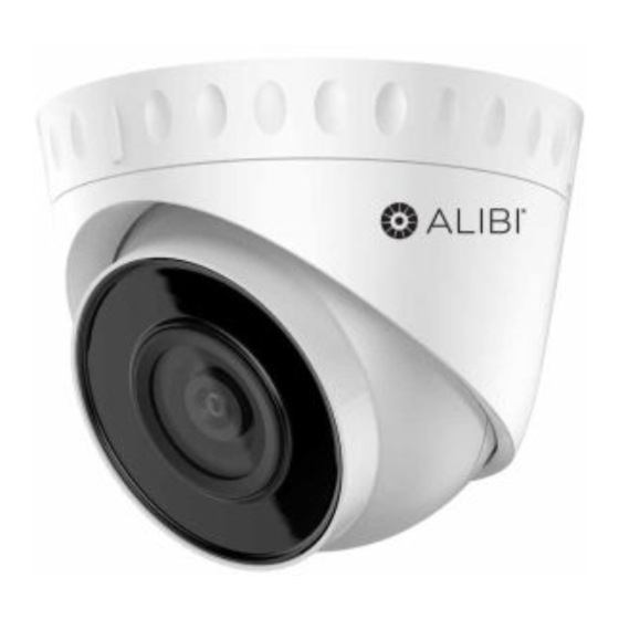
ALI-NS2002R 2 Megapixel IP Turret
Camera Quick Installation Guide
This document guides you through the basic steps to install and configure the ALI-NS2002R camera. This
camera features:
2 Megapixel, 1/2.8" progressive scan CMOS sensor, 1920 × 1080 pixels @ 30 fps
•
2.8 mm lens with 114° horizontal field of view
•
Dual-stream video support , ONVIF compatible
•
Video stream compression: H.265+, H.265, H.264+, H.264 standard and MJPEG
•
Color: 0.01 Lux @ (F1.2, AGC ON), 0.028 Lux @ (F2.0, AGC ON) minimum illumination
•
Digital Wide Dynamic Range (WDR) and BLC
100 ft IR range
•
Dual power capable - Power over Ethernet (PoE) or 12 Vdc
•
IP67 weatherproof rating
•
Compatible with ALI-AB1 and ALI-AJ1 junction boxes. See Specifications.
•
For more information, refer to these documents - available from your equipment vendor:
ALIBI™ Tools Utility Installation software and User Manual
•
ALIBI™ Witness App for Android Quick Start Guide
•
ALIBI™ IP Camera Firmware Version 5.4 User Manual (or later) provided at:
•
AlibiSecurity.com/resources
•
Mounting
base
Alignment
mark
Enclosure
Camera
body
ALI-NS2002R camera
Mounting
base
Drop
cable
Mounting
screw
holes (3)
Mounting base - mounting surface
www.observint.com
1
What's in the box
Box contains:
Installation Guide
•
Drill template
•
Weatherproof Ethernet
•
fitting
Mounting screws and
•
wall inserts
Step 1.
Route interface cables to the camera
Ethernet and power interface cables connect directly to the camera drop cable (see photo above). A ground
terminal is provided on the mounting surface side of the camera base (see photo above).
The ALI-AB1, ALI-AJ1 and ALI-AJ6 junction boxes are compatible with the camera. If using a junction box,
connectors between the camera drop cable and extension cables should be stored within the box.
When selecting a mounting location for the camera
• Make sure that there are no reflective surfaces near to the camera lens. IR light from the camera may
bounce back onto the lens causing reflections.
Orientation
NOTE
mark "UP"
• Determine how wiring is routed into the camera. The cable can be routed through conduit (a threaded
conduit adapter is provided), through the mounting surface and access hole in the mounting plate, or
through the side inlet.
The camera includes connectors for the following:
Ethernet (required): The Ethernet drop cable can connect to a LAN extension cable from a switch
•
or Network Video Recorder. The camera can be powered across the LAN using power over Ethernet
Lens
(PoE) injection. See the Specifications section at the end of this document for power requirements.
12 Vdc power input (optional if PoE powered, required if not): Refer to the Specifications section
•
of this document for voltage and current requirements. ALWAYS COMPLY WITH THE POLARITY
SHOWN IN THE PICTURE ABOVE.
Ground: A ground terminal is provided camera body for attaching an earth ground cable. See the
•
photos above. Always ground the camera if it is installed in a moist or humid environment. Follow
Mounting
local electrical codes for proper grounding.
base
This camera includes the TVS 2000V lightning protection feature. To use this feature, refer to the
Camera
NOTE
body
TVS 2000V section at the end of this document for implementation guidelines.
Ground
1.
Route a LAN extension cable from a network switch or Network Video Recorder (NVR) to where the
terminal
camera will be installed.
2.
If the camera is not powered using PoE, route 12 Vdc power extension cables from an adequate
power source to the location where the camera will be installed.
3.
You can attach an earth ground extension cable to the junction box. Route the cable to the location
of the junction box, if needed. Always follow local electrical codes when using an earth ground.
CAUTION
Step 2.
Install the camera
An ALI-NS2002R camera can be mounted directly to a wall or ceiling, or with a junction box. The surface
should support at least four times the weight of the camera and junction box (if used). The video/power
drop cable from the camera can be routed either through mounting surface or through a cable channel in
the mounting base.
12 Vdc Power connector with plug
Ethernet connector - PoE capable
Camera drop cable connectors
Weatherproof fitting
for Ethernet cable
Do not apply power to the camera at this time. Before applying power to the camera, ensure that
the polarity is correct. An incorrect connection may cause a malfunction and can damage the
camera.
Mounting screws
and wall inserts
ALI-NS2002R_CQ
191015
Advertisement
Table of Contents

Related Manuals for ALIBI ALI-NS2002R


Summary of Contents for ALIBI ALI-NS2002R
- Page 1 Step 2. Install the camera An ALI-NS2002R camera can be mounted directly to a wall or ceiling, or with a junction box. The surface Mounting base - mounting surface should support at least four times the weight of the camera and junction box (if used). The video/power drop cable from the camera can be routed either through mounting surface or through a cable channel in the mounting base.
- Page 2 What you need Using the ALI-AJ6 box as a guide, mark and then drill three holes for the screws that will attach the box to the wall or ceiling. If the extension cables will be routed into the box through the mounting To install the camera, you will need: surface, also drill a hole for the extension cables.
- Page 3 See below. Edit Network Parameters In the screen above, the tool can discover devices on other sub-nets. It will also list other Alibi compatible In the popup window, edit the current network parameters, and then enter the Administrator NOTE devices on the LAN, and devices with the address 192.168.1.64 (an inactive Alibi device).
- Page 4 Click OK to save your settings. The parameter change(s) will be shown device’s network parameters (see below). Step 7. Login to the camera NOTE: If the camera LAN extension cable is attached to a Network Video Recorder (NVR), skip this step. Microsoft®...
- Page 5 Up to 32 users 3 levels: Administrator, Operator and User 0° ~ 75° Client Alibi Central Management Software (ACMS) v3.1 or later, ACMS-XP Rotation adjustment: If necessary, rotate the camera body within the enclosure to produce a Web Browser Microsoft ©...
- Page 6 Power Consumption and 12 Vdc: 0.4 A, max. 5 W; Current PoE: (802.3af, 36 V ~ 57 V), 0.2 A ~ 0.1 A, max. 6.5 W Protection Level IP67 weatherproof rating Material Plastic and metal Dimensions Φ4.3” × 3.7” (Φ110 mm × 93.2 mm) Camera: approx.
Need help?
Do you have a question about the ALI-NS2002R and is the answer not in the manual?
Questions and answers