Table of Contents
Advertisement
Quick Links
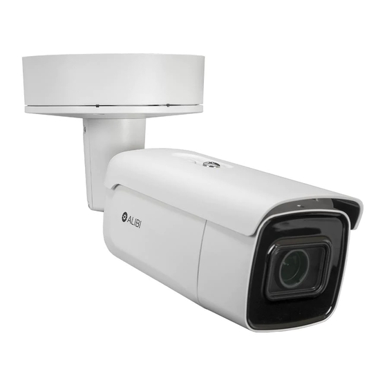
This document guides you through the basic steps to install and configure the ALI-NS4114R network
vari-focal bullet camera. This camera features:
1/2.5" 2560 × 1440 pixel Progressive Scan CMOS sensor
•
2.8 ~ 12 mm motorized vari-focal lens
•
Low light 0.008 lux color minimum illumination
•
H.265, H.265+, H.264+, H.264 video compression
•
120 dB Wide Dynamic Range
•
Back light compensation (BLC) / 3D dynamic noise reduction (DNR)
•
IP67 weatherproof, IK10 vandalproof rated
•
4 behavior analyses and face detection
•
For more information, refer to these documents - available from your equipment vendor:
ALIBI™ Tools Utility Installation and User Manual
•
ALIBI™ Witness 2.0 r3 App for Android or iOS Quick Start Guide
•
ALIBI™ IP Camera Firmware Version 5.4 User Manual (or later) provided at:
•
AlibiSecurity.com/resources
Adjustment
bracket
Camera body
Maintenance panel
Screw stud for
junction box (3)
Holes (4) for
surface mounting
or double-gang
box (#1)
Hole for surface
or gang box
cable routing
Sealing plug
for interface wiring (5)
Sealing plug
for LAN/PoE cable
Junction box (adapter plate side)
1
www.observint.com
ALI-NS4114R 4MP Vari-focal IP Bullet Camera Quick Installation Guide
Adapter plate
Junction box
Junction box screw (4)
Lens
Holes (2) for
single-gang box
mounting (#2)
Adapter plate
Ground terminal
Side inlet with
conduit adapter
Side inlet
cover
Captive screws
connect to
adapter plate (3)
Safety cable
Interface terminals
for alarms, audio,
LAN, power
Hook for safety cable
Sun shield
Adjustment
bracket lock
screw
What's in the box
Your camera includes the items shown below.
Mounting hardware
Step 1.
Route wiring to the camera
Interface cables can be routed into the camera either through the adapter plate (through the mounting
surface or through a gang box), through the side inlet of the junction box, or through conduit.
When selecting a mounting location for the camera
• Make sure that there are no reflective surfaces near to the camera lens. IR light from the camera may
bounce back onto the lens causing reflections.
NOTE
• Determine how wiring is routed into the camera. The cable can be routed through conduit
(a threaded conduit adapter is provided), through the mounting surface and access hole in the
mounting plate, or through the side inlet.
See photos above. The camera includes connectors for the following:
Ethernet (required): The Ethernet drop cable can connect to a LAN extension cable from a
•
switch or Network Video Recorder. The camera can be powered across the LAN using power over
Ethernet (PoE) injection. See the Specifications section at the end of this document for power
requirements.
12 Vdc power input (optional if PoE powered, required if not): If powering the camera
•
with a long power extension cable, refer to the tables at the end of this guide for wire gauge
requirements. Voltage input at the camera can be within the range 12 Vdc ± 25%.
Junction box (inside view)
Back of camera (junction box removed)
Conduit adapter
Security L-wrench
Insertion tool
Junction box screws
Sealing plug
for interface
wiring (5)
Conduit
adapter
Side inlet
cover
BNC video
maintenance
cable
ALI-NS4114R_CQ
180410
Advertisement
Table of Contents

Related Manuals for ALIBI ALI-NS4114R


Summary of Contents for ALIBI ALI-NS4114R
- Page 1 ALI-NS4114R 4MP Vari-focal IP Bullet Camera Quick Installation Guide This document guides you through the basic steps to install and configure the ALI-NS4114R network Captive screws Sealing plug connect to for interface vari-focal bullet camera. This camera features: adapter plate (3) wiring (5) 1/2.5”...
-
Page 2: Install The Camera
Install the adapter plate Alarm IN/OUT, Audio IN/OUT (optional): Connect these leads to auxiliary devices as needed. • The camera supports one alarm input, one alarm output, one audio input and one audio output. The camera can be mounted onto a wall or ceiling, or onto a single-gang or double-gang electrical box. Audio IN and OUT terminations require 3.5 mm standard audio plugs. -
Page 3: Junction Box
Refer to the documentation available for your NVR firmware for the procedure to activate the camera, if necessary. When an Alibi device is first installed, or reset to its factory configuration, it must be “Activated” before it can be used. In the Alibi Configuration Tool, “Inactive” devices have a Security status of Inactive, and an IPv4 address of 192.168.1.64. -
Page 4: Step 5. Modify Network Parameters
Enable DHCP: You can select Enable DHCP to acquire compatible network settings from a DHCP server installed on the LAN. However, these settings can be changed by the DHCP server. Since it is recommended to use an unchanging IP address, you can use DHCP Activate to acquire compatible network settings, and then uncheck Enable DHCP and save that configuration to retain the new network parameters. -
Page 5: Logout Button
Run as administrator The Live View screen with the camera video image should appear. Screen select tabs Live View image Logout button To login to the camera from a computer on the same LAN: Open your Microsoft Internet Explorer (IE) browser on your computer and enter the IP address of the camera in the URL field. -
Page 6: Specifications
Refer to the firmware user manual for your NVR to use the other submenus on this screen. Zoom In / Out Specifications Focus In / Out Iris Open / Close Camera ALI-NS4114R Image Sensor 1/2.5” Progressive Scan CMOS Signal System PAL / NTSC Color: 0.008 lux @ (F1.2, AGC ON), 0.016 lux @ (F1.6, AGC ON), In the PTZ Control panel, click the zoom and focus buttons labeled in the graphic above. -
Page 7: Wire Gauge Standards
Up to 32 users, 3 levels: Administrator, Operator and User 20 (6) 32 (9) 49 (14) 128 (37) Client Alibi Central Management System (ACMS) V3.1 (or later) 19 (6) 31 (9) 47 (13) 123 (35) Web browser Microsoft® Internet Explorer® Version 11 (or later)
Need help?
Do you have a question about the ALI-NS4114R and is the answer not in the manual?
Questions and answers