Table of Contents
Advertisement
Quick Links
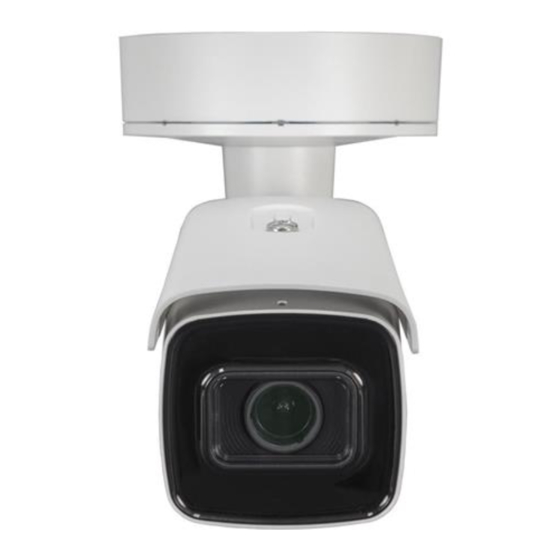
ALI-NS4128R 8 MP IP Varifocal 170 ft IR
Bullet Camera Quick Installation Guide
This document guides you through the basic steps to install and configure the ALI-NS4128R IP bullet
camera. This camera features:
8MP 3840 × 2160 (4K) resolution @ 20 fps
•
STARLIGHT Color: 0.008 Lux @ (F1.2, AGC ON), 0.014 Lux @ (F1.6, AGC ON) minimum illumination
•
170 ft Full Fraime IR
•
2.8 ~ 12 mm motorized zoom
•
Supports H.265+ / H.265 / H.264+ / H.264 / MJPEG compression
•
120 dB Wide Dynamic Range
•
Supports microSD/SDHC/SDXC card onboard storage up to 128GB max (card not included)
•
IP67 weatherproof rated, IK10 impact resistant
•
ONVIF Profile S & Profile G, ISAPI
•
For more information, refer to these documents - available from your equipment vendor:
ALIBI™ Witness App for Android Quick Start Guide
•
ALIBI™ IP Camera Firmware Version 5.4 User Manual (or later) provided at:
•
AlibiSecurity.com/resources
Bracket lock
screw
Adjustment
bracket
Camera body
Maintenance panel
Screw stud for
junction box (3)
Holes (4) for
surface mounting
or double-gang
box (#1)
Hole for surface
or gang box
cable routing
Sealing plug
for interface wiring (5)
Sealing plug
for LAN/PoE cable
Junction box (adapter plate side)
1
www.observint.com
Adapter plate
Junction box
Junction box screw (4)
Lens
Front arrow
Holes (2) for
single-gang box
mounting (#2)
Adapter plate
Ground terminal
Side inlet with
conduit adapter
Side inlet
cover
Captive screws
connect to
adapter plate (3)
Safety cable
Interface terminals
for alarms, audio,
LAN, power
Sun shield
Hook for
safety cable
What's in the box
Your camera includes the items shown below.
Mounting hardware
Step 1.
Route wiring to the camera
Interface cables can be routed into the camera either through the adapter plate (through the mounting
surface or through a gang box), through the side inlet of the junction box, or through conduit.
When selecting a mounting location for the camera
• Make sure that there are no reflective surfaces near to the camera lens. IR light from the camera may
bounce back onto the lens causing reflections.
NOTE
• Determine how wiring is routed into the camera. The cable can be routed through conduit
(a threaded conduit adapter is provided), through the mounting surface and access hole in the
mounting plate, or through the side inlet.
See photos above. The camera includes connectors for the following:
Ethernet (required): The Ethernet drop cable can connect to a LAN extension cable from a
•
switch or Network Video Recorder. The camera can be powered across the LAN using power over
Junction box (inside view)
Back of camera (junction box removed)
Conduit adapter
Security L-wrench
Insertion tool
Junction box screws
Sealing plug
for interface
wiring (5)
Conduit
adapter
Side inlet
cover
BNC video
maintenance
cable
ALI-NS4128R_CQ
190904
Advertisement
Table of Contents

Related Manuals for ALIBI ALI-NS4128R


Summary of Contents for ALIBI ALI-NS4128R
- Page 1 (3) wiring (5) Conduit adapter This document guides you through the basic steps to install and configure the ALI-NS4128R IP bullet camera. This camera features: 8MP 3840 × 2160 (4K) resolution @ 20 fps • STARLIGHT Color: 0.008 Lux @ (F1.2, AGC ON), 0.014 Lux @ (F1.6, AGC ON) minimum illumination •...
-
Page 2: Install The Camera
Ethernet (PoE) injection. See the Specifications section at the end of this document for power Adapter plate screw (3) Junction box screw (4) requirements. 12 Vdc power input (optional if PoE powered, required if not): If powering the camera • with a long power extension cable, refer to the tables at the end of this guide for wire gauge requirements. -
Page 3: Junction Box
Hook the safety cable on the junction box onto the tang in the camera module and allow the camera to hang freely. In the screen above, the tool can discover devices on other sub-nets. It will also list other Alibi NOTE compatible devices on the LAN, and devices with the address 192.168.1.64 (an inactive Alibi device). -
Page 4: Login To The Camera
Activate Selected Click the Activate button. In the Activate window, you will create a password for the admin Click OK to save your settings. The parameter change(s) will be shown device’s network (administrator) username. parameters (see below). In the Activate window, enter an a password for admin in the New Password field. Step 6. -
Page 5: Logout Button
Screen select tabs Live View image Logout button Capture, Record, Zoom icons In the login window, enter admin for the User Name and the password you created in the Password field, the click Login. Step 7. Adjust the camera for your surveillance target If this is the first time you are logging into a camera, you may see the message in the following While observing live video from your camera in the Live View tab (see above), loosen the bracket screen. - Page 6 If using Auto-Switch, open the Day/Night Switch submenu to select the The microSD card may need to be initialized before it can be used to record data. Click the Setup tab, then click the Storage link in the left frame. Click Storage Management in Sensitivity, Filtering Time, and Smart IR feature ON or OFF.
- Page 7 Click the Save button at the bottom of the menu to retain your settings. Scene Change Detection Smart Event setup Scene change detection feature detects the change of surveillance field of view affected by the external factors such as the intentional rotation of the camera. This alarm can trigger actions performed by the camera to report and record the alarm information.
- Page 8 Threshold: Range [0-10]s, the threshold for the time of the object loitering in the region. Set the Sensitivity value as needed. Sensitivity represents the percentage of the If you set the value as 0, alarm is triggered immediately after the object entering the body part of an acceptable target that crosses the pre-defined line.
-
Page 9: Specifications
Click Linkage Method to select the linkage methods options menu. To configure the Linkage Specifications Methods menu, check the select boxes for the options you want to use. Click the Save button to retain your settings. Camera ALI-NS4128R Image Sensor: 1/2” Progressive Scan CMOS Region Exiting Detection Smart Event setup Min. Illumination: Color: 0.008 Lux @ (F1.2, AGC ON), 0.011 Lux @ (F1.4, AGC ON) - Page 10 3 levels: Administrator, Operator and User Client Alibi Central Management Software (ACMS) ver. 3.1 or later, ACMS-XP Fit the end cap on the network cable onto the camera drop End cap cable end cap. Rotate the network cable end cap to lock it in...
Need help?
Do you have a question about the ALI-NS4128R and is the answer not in the manual?
Questions and answers