Table of Contents

Related Manuals for FlowLine EchoSonic II LU23 Series


Summary of Contents for FlowLine EchoSonic II LU23 Series
- Page 1 EchoSonic® II Ultrasonic Level Transmitter LU23, LU27, LU28 & LU29 Series Manual NEMA 4X Enclosure Flowline Inc. 10500 Humbolt Street Los Alamitos, CA 90720 Tel: (562) 598‐3015 Fax: (562) 431‐8507 www.flowline.com Rev A1 MN300480 1 of 24 ...
-
Page 2: Table Of Contents
INTRODUCTION / TABLE OF CONTENTS Step One The EchoSonic® II is a general‐purpose ultrasonic level transmitter that provides a loop powered 4‐20 mA output. The 4‐20 mA output can be used to provide the proportional level of liquid in any tank or vessel. The signal can be connected to any device that accepts loop powered 4‐20 mA signals, such as a PLC, SCADA, DCS, display, controller, etc. New Features Simple configuration with WebCal® software, no more target calibration. Adjustable Loop Fail‐Safe, Hold Last, Empty, Full, 21 mA, 22 mA Easy to reverse mA output, 4‐20 mA to 20‐4 mA Adjustable start‐up condition, Empty, Mid (12 mA), Full, Over range (22 mA) Table of Contents Specifications: .............................. 3 Dimensions: .............................. 3 About this manual: ............................ 4 Components: .............................. 5 Getting Started: .............................. 6 ... -
Page 3: Specifications
SPECIFICATIONS/DIMENSIONS Step Two Range: LU27: 4" to 9.8' LU23: 8" to 18.0' LU28: 8" to 26.2' LU29: 8" to 32.8' (10 cm to 3 m) (20 cm to 5.5 m) (20 cm to 8 m) (20 cm to 10 m) Accuracy: ± 0.2% of range Models: LU23‐4_, LU23‐5_, Resolution: LU27: 0.019” (0.5mm) LU28‐4_, LU28‐5_, LU29‐4_ & LU29‐5_ LU23: 0.039” (1mm) LU28: 0.079” (2 mm) LU29: 0.079” (2 mm) Dead band: LU27: 4” (10cm) LU23/28/29: 8” (20cm) Beam width: LU27: 2” (5cm) LU23/28/29: 3” (7.6cm) Configuration: WebCal® PC Windows® USB® 2.0 Memory: Non‐volatile Supply voltage: ... -
Page 4: About This Manual
SAFETY PRECAUTIONS Step Three About this Manual: PLEASE READ THE ENTIRE MANUAL PRIOR TO INSTALLING OR USING THIS PRODUCT. This manual includes information on the EchoSonic® II series Ultrasonic Level transmitter from FLOWLINE. Please refer to the part number located on the sensor label to verify the exact model configuration, which you have purchased. User’s Responsibility for Safety: FLOWLINE manufactures a broad range of level sensing technologies. While each of these sensors is designed to operate in a wide variety of applications, it is the user’s ... -
Page 5: Components
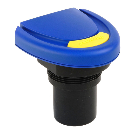
COMPONENTS Step Four Components: EchoSonic® II is offered in four different models. Depending on the model purchased, you may or may not have been shipped all the components shown below. You do however, need an EchoSonic® II, USB® Fob and Viton® gasket to configure, install and operate EchoSonic® II. P/N Max. Range Dead Band Thread Fob LU23‐40 No Fob 2” NPT LU23‐41 Fob Included 18.0’ (5.5m) 8” (20cm) LU23‐50 No Fob ... -
Page 6: Getting Started
GETTING STARTED Step Five EchoSonic® II is configured through WebCal®*, a PC software program. WebCal® is a free download from Flowline’s website. You must download and install WebCal® prior to plugging in the USB® Fob. Please go to www.flowline.com/webcal‐software, and select your language version. WebCal® System Requirements Windows® XP, Vista, 7, 8, 10 32 or 64‐bit system 1 USB® 2.0 port 10 mB hard drive space 256 mB RAM Internet connection * For complete information on the WebCal® software, please refer to the WebCal® manual located at ... -
Page 7: Usb® Fob Interface
Once EchoSonic® II is configured and prior to installation, isolate the white and green wires from active power to prevent a short of the configuration circuit Note: When using the Fob, do not add VDC power. The Fob, when connected to the computer, will provide the required power to the EchoSonic® II. * For complete information on the WebCal® software, please refer to the WebCal® manual located at www.flowline.com ® Note: EchoSonic II ships with the LI99‐2001 Fob (white in color). The LI99‐1001 Fob (black in color) can be ... -
Page 8: Step 1: Sensor Configuration
Step Five With EchoSonic® II connected to your computer, open the WebCal®* software by clicking on the WebCal® icon. Follow steps 1‐4 to configure the transmitter. Click “Help” in the lower right hand corner and open the help menu of WebCal® for additional instructions on WebCal®. If you need additional assistance using WebCal®, please contact a Flowline applications engineer at (562) 598‐3015. * For complete information on the WebCal® software, please refer to the WebCal® manual located at www.flowline.com/webcal‐software. Configuring EchoSonic® II with WebCal® 1. Sensor Configuration a. Configures the Loop Fail‐Safe, Output at Empty and Startup condition for the sensor. ... - Page 9 GETTING STARTED (continued) Step Five Tank Shape Selection: Defines the shape of the tank as well as the dimensional information for the tank with respect to the sensor’s location on the tank. Tank Level Configuration: The Height Units, Sensor Height, Fill‐Height and Capacity were all calculated in the previous Dimensional Entry window. To adjust these settings, click on Select Tank Shapes. Rev A1 MN300480 9 of 24 ...
- Page 10 Write to Unit – This WebCal®* operation uploads configuration into the sensor, provides a custom wiring diagram specific to the signal output and/or relay configuration, and saves the configuration file to your hard drive. * For complete information on the WebCal® software, please refer to the WebCal® manual located at www.flowline.com/webcal.php. 10 of 24 MN300480 Rev A1 ...
-
Page 11: Wiring
ING Step Six Wiri ng Diagram Wiri ng EchoSon nic® II: Once e EchoSonic ® II has bee en configure ed, follow th he Wiring Di agram by th he WebCal® ® softw ware. A ty ypical wiring g diagram is shown a bove. Flow wline recom mmends usi ng a qualif fied licensed d ... -
Page 12: Voltage Output
WIRING (continued) Step Six General notes for electrical connections, usage and safety: Where personal safety or significant property damage can occur due to a spill, the installation must have a redundant backup safety system installed. Wiring should always be completed by a licensed electrician. Supply voltage should never exceed 28 VDC. Protect the sensor from excessive electrical spikes by isolating the power, whenever possible. The sensor materials must be chemically compatible with the liquids to be measured. Design a fail‐safe system for possible sensor and/or power failure. Never use the sensor in environments classified as hazardous. Voltage Output: EchoSonic® II can be used as a 0 to 5 or 0 to 10 VDC output device. A resistor will need to be added to the circuit to enable a voltage output (refer to the wiring diagram below). 0‐5 VDC output o Add a 250 Ohm resistor o Actual output will be 1 to 5 VDC 0‐10 VDC output o Add a 500 Ohm resistor o Actual output will be 2 to 10 VDC 12 of 24 MN300480 Rev A1 ... -
Page 13: Wiring To Displays, Controller's & Plc's
WIRING (continued) Step Six Wiring to Display, Controllers & PLC’s Below is a quick review of wiring the EchoSonic® II to common display, controllers and PLC’s. DataView™ LI55 Series Commander™ LI90 Series Level Controller Multi‐Tank Level Controller DataLoop™ LI23 Series DataLoop™ LI23 Series Level Indicator Level Indicator without the backlight with the backlight Rev A1 MN300480 13 of 24 ... - Page 14 WIRING (continued) Step Six Wiring to Display, Controllers & PLC’s (continued) DataPoint™ LC52 Series DataPoint™ LC52 Series Level Controller Level Controller JWA mode (Factory Setting) JWB mode Generic Loop Generic PLC Powered Display 14 of 24 MN300480 Rev A1 ...
-
Page 15: Installation
INSTALLATION Step Seven The EchoSonic® II should always be mounted perpendicular to the liquid surface and installed using the provided Viton® mounting gasket. Make sure that the fitting and transmitter threads are not damaged or worn. Always hand‐tighten the transmitter within the fitting. Perform an installed leak test under normal process ... -
Page 16: Fitting Selection
INSTALLATION (continued) Step Seven Fitting Selection: Check the part number to determine the required fitting mount size and thread type. EchoSonic® II is commonly installed in tank adapters, flanges, brackets or standpipes. Note: Always include the gasket when installing the EchoSonic® II. 1. Tank Adapter: Select a tank adapter fitting, such as the LM52‐1890 for the LU27 series or the LM52‐ 2890 for the LU23, LU28 & LU29 series. a. For best results, select a 2” tank adapter and add a reducer bushing such as the LM52‐1400, thread x thread, reducer bushing. ... -
Page 17: Flange
INSTALLATION (continued) Step Seven 3. Flange (LU27 series): If installing on a flange, select a flange with a thread that is above the plane of the flange, such as the LM52‐1850. a. The LU23, LU28 & LU29 series works well with Flange installations. b. Avoid the use of blind flanges with tapped threads or flanges where the threads are even with the plane of the flange, such as the Banjo 1" Poly ANSI Flange (series AF100). c. Use a flange with a 2” thread and add a 2” to 1” reducer bushing to complete the installation. 2” Flange w/ 2” Flange w/ 2” Flange w/ thread out of plane thread in plane Reducer Bushing (LM52‐1850) (w/LM52‐1800) Do not use thread in plane 4. Side Mount Bracket: For installations in open tanks and sumps, use the LM50 series side mount bracket. a. For the LU27 series, order the LM50‐1001‐1, which includes a 2”x 1” Reducer Bushing. b. For the LU23, LU28 & LU29, series, order the LM50‐1001 side mount bracket. LM52-1001 Shown LM52-1001-1 Shown Note: The Side Mount Bracket (LM50 series) is not designed for use with stand pipes or as a method to secure stand pipes. There are too few threads to properly hold the sensor and the stand pipe. Rev A1 ... - Page 18 INSTALLATION (continued) Step Seven 5. Stand Pipe: A standpipe maybe used to dampen turbulence or when foam is present in the application. a. Pipe can be made of any material. b. Minimum ID for the stand pipe is listed below. i. A 2” pipe (min. pipe ID) is usable with the LU27 series. ii. A 3” pipe (min. pipe ID) is usable with the LU23, LU28 & LU29 series. iii. Pipes larger than 3” can also be used. c. Use a coupling and reducer bushing to attach the EchoSonic® II to the pipe. ...
-
Page 19: Advanced Feature
This tool is designed to help solve operational issues. Changing these setting will alter the performance of your unit. Please read through this HELP file to assist you in making adjustments or if still unclear about a specific issue, please contact FLOWLINE, Applications Engineering. ... -
Page 20: Appendix
APPENDIX Step Nine Update and Demo Tabs: WebCal® has two other page tabs which can be used to assist in the configuration of the EchoSonic® II. These page tabs are the Updates and Demo tabs. Updates: The Updates tab has two key features. The first is the ability to update the WebCal® software to its latest version. The second is the ability to update EchoSonic® II’s firmware to its latest version. Demo: The Demo tab has the ability to test the EchoSonic® II sensor against a fixed target and can be used to confirm the switching points for the relays. Note: this feature is only a simulation and the relays are not physically opening and closing. 20 of 24 MN300480 Rev A1 ... -
Page 21: Factory Defaults
APPENDIX (continued) Step Nine Factory Default: Pressing the Factory Config button in the Configuration menu will return the screen to the following settings. Out of the box, the EchoSonic® II will output a 4‐20 mA output that is maximized for its operational range. The transmitter can be used in the original factory setting without configuration with WebCal®. Use the table below to identify the configuration of the sensor out of the box. Factory Defaults Table Part Sensor Fill Loop Output Startup Number Height Height Fail‐Safe at Empty Condition LU27‐_ _ 300 cm 290 cm Overfill 4 mA @ Empty Series ... -
Page 22: User Settings
APPENDIX (continued) Step Nine Testing the Transmitter 1. Connect a multimeter in series with the black wire to read the current output. 2. Verify that the current increases (tank filling) and decreases (tank emptying) appropriately in the calibrated span. 3. If not, carefully observe and attempt to correlate any installation, level or application event for more specific troubleshooting direction. User Settings: Fill out the chart below and keep as a record of your configuration. Tank Height = Fill‐H = Loop Fail‐Safe (select one) Hold Last Value Empty Full Overfill (21mA) Overfill (22mA) Output at Empty (select one) 4mA at Bottom 20mA at Bottom Startup Condition (select one) Empty Mid‐Tank (12mA) Full Tank Overfill (22mA) Advanced (if selected, identify which filter that was activated) Increase output filtering: Decrease output filtering: Stabilize output in dead band ... -
Page 23: Troubleshooting
Check in Device Manager that both drivers (WebCal® Configuration & EchoFob) are present. Internet error. The server This is a warning indicating the computer configuring EchoSonic® II is name or address could not not connected to the internet. Click OK to continue. Flowline be resolved. recommends being connecting to the internet for all configurations. Not being connected to the internet will not prevent the EchoSonic® II from being configured. ... -
Page 24: Warranty
WARRANTY, RETURNS AND LIMITAITONS Step Ten Warranty Flowline warrants to the original purchaser of its products that such products will be free from defects in material and workmanship under normal use and service in accordance with instructions furnished by Flowline for a period of two years from the date of manufacture of such products. Flowline's obligation under this ...
Need help?
Do you have a question about the EchoSonic II LU23 Series and is the answer not in the manual?
Questions and answers